E
2
Controller
Operation Manual
Microprocessor Controller for STULZ Branded
Precision Air Conditioners and Air Handlers

QUICK START INSTRUCTIONS
FOR INITIAL START-UP,
SEE SECTION 3.3
Starting the A/C System
Notice
This document contains information protected by copyright. All rights are reserved. The owner of the
equipment for which this manual is written may photocopy the contents of this manual for internal
use only. No part of this document may be photocopied, reproduced, or translated into another
language for use by anyone other than the owner of the equipment for which this manual is written
without the prior written consent of STULZ Air Technology Systems, Inc. (STULZ).
This document contains confidential and proprietary information of STULZ Air Technology Systems,
Inc. Distributing or photocopying this document for external distribution is in direct violation of
United States copyright laws and is strictly prohibited without the express written consent of STULZ.
Unpublished rights reserved under the copyright laws of the United States and of other countries.
Other brands and trade names are trademarks of their respective owners.
© 2020 STULZ Air Technology Systems, Inc.
Printed in the United States of America.
All rights reserved.
STULZ Air Technology Systems, Inc.
1572 Tilco Drive
Frederick, MD 21704 USA
https://www.stulz-usa.com
iii
E2
Series Controller Operation Manual
Table of Contents
1.0
GENERAL INFORMATION ........................... 1
1.1
Forward ......................................................................... 1
1.2
Safety Summary .......................................................... 1
1.3
Warnings and Cautions ............................................. 1
2.0
DESCRIPTION ............................................ 2
2.1
Features ........................................................................ 2
2.1.1
Field Configurable ...................................................... 2
2.1.2
Password Protection ................................................. 2
2.1.3
BMS Interface .............................................................. 2
2.1.4
User Interface Terminals .......................................... 3
2.1.5
Graphic Terminal ........................................................ 3
2.1.6
Function Keys .............................................................. 3
2.1.7
Alarms ............................................................................ 3
2.1.8
Contrast Adjustment ................................................. 3
2.1.9
Large Bezel Terminal .................................................... 4
2.3.2 Large Bezel Touch Screen Terminal ......................... 6
2.3.4 Alarms ............................................................................ 6
2.3.5 LCD Display Screen .................................................... 6
2.3.6 Navigating Menu Screens ......................................... 6
2.3.7 Graphs Menu ................................................................ 6
2.4 Controller Models ........................................................ 6
2.4.1 GEN 1 Controller Layout ........................................... 6
2.4.2 GEN 2 Controller Layout ........................................... 7
2.4.3 Expansion I/O Modules ............................................. 7
2.4.4 Constant Contact UPS Module ............................... 7
2.4.5 EVD Module .................................................................. 7
3.0
Startup....................................................... 8
3.1
Navigating Controller Screens ................................ 8
3.1.1
Menu Selection ............................................................ 8
3.1.2
Menus ............................................................................. 8
3.1.3
Display Variables ......................................................... 9
3.1.4
Cursor Position in Screens ....................................... 9
3.1.5
Modifiable Variables ................................................... 9
3.2
Password Authorization Levels ............................... 9
3.2.1
Password Protected Screens .................................. 9
3.2.2
Wrong Password ...................................................... 10
3.2.3
Setting the Passwords ............................................ 10
3.3
Starting the A/C System ........................................ 10
3.4
Setpoint Adjustment ................................................ 11
3.5
Saving and Restoring Setpoint Parameters ..... 12
3.6
Alarms .......................................................................... 12
3.6.1
Summary Alarm ......................................................... 12
3.6.2
Customer Alarms ...................................................... 13
3.6.3
Custom Alarms .......................................................... 13
4.0
Operation ................................................ 14
4.1
General ........................................................................ 14
4.2
Temperature/Humidity Sensors ..........................14
4.2.1
Economizer Air Sensors.......................................... 14
4.3
Control Signals .......................................................... 14
4.3.1
On/Off Digital Control ............................................. 14
4.3.2
Proportional/Integral (P/I) Control ..................... 14
4.4
Temperature/Humidity Control ...........................14
4.4.1
Dewpoint Control ..................................................... 14
4.5
Operating Configurations ...................................... 15
4.5.1
Cooling ......................................................................... 15
4.5.1.1
Chilled Water/AWS/FC .......................................... 15
4.5.1.2
Compressor Based Direct Expansion (DX) .......15
4.5.1.2.1 Electronic Expansion Valve .................................... 15
4.5.2
Energy Savings Configurations ........................... 15
4..5.2.1
Economizer ...................................................................16
4.5.2.2
Alternate Water Source Cooling (AWS) ............. 16
4.5.2.3
Free Cooling (FC) ..................................................... 17
vi
E2 Series Controller Operation Manual
4.5.3
Heating ........................................................................ 17
4.5.4
Humidifying ................................................................ 17
4.5.4.1
Humidifying With Proportional Control ............. 17
4.5.5
Dehumidifying ........................................................... 17
4.5.5.1
Reheat ......................................................................... 17
4.6
Airflow/Fan Speed Control .................................... 17
4.6.1
Anti-Backdraft Mode (Optional) ........................... 18
4.6.2
Underfloor/Cold Aisle Pressure Control ........... 18
4.6.3
Modbus Fan Control (Optional) ............................ 18
4.6.4
Suction Pressure Fan Speed Control (O). ......... 19
4.7
Communication With the Controller....................19
4.8
Remote On/Off ......................................................... 19
4.9
Weekly Timer .............................................................19
4.10
Dual Power Transfer Switching ........................... 19
4.10.1
Power Transfer Performed by Phase Monitors 19
4.10.2
Power Transfer Performed by System
Controller.................................................................... 20
4.11
Tandem Compressors Operation ........................ 20
4.12
Shadow Units ............................................................ 20
v
E2
Series Controller Operation Manual
5.0
Menu Screens .......................................... 22
5.1
Main Menu .................................................................. 22
5.2
Information Menu ..................................................... 22
5.2.1
Operating Conditions .............................................. 22
5.2.2
Shadow Unit Alarms ................................................ 23
5.2.3
Return Sensor ........................................................... 23
5.2.4
Compressor Status- (DXbased systems) .......... 23
5.2.4.1
Optional Compressor Status Fields .................... 23
5.2.4.2 Remote Sensor ......................................................... 24
5.2.5
Remote Temperatures ............................................... 24
5.2.6
Water Temperature.................................................. 24
5.2.7
Setpoint Values ............................................................ 24
5.2.8
Fans and CW Valve ..................................................... 24
5.2.9
Economizer Information Menu Screens ............ 23
5.2.10
Under Floor Pressure .............................................. 23
5.2.11
Differential Air Pressure Sensor ........................... 23
5.2.12
Dewpoint Sensor ...................................................... 23
5.2.13
Air Speed Sensor...................................................... 23
5.2.14
User Sensors ............................................................. 24
5.2.15
KVA Display ................................................................ 24
5.2.16
Differential Water Pressure ................................... 24
5.2.17
Air Flow Rate ............................................................. 24
5.2.18
Water Flow Rate ....................................................... 24
5.2.19
Atmospheric Pressure ............................................ 24
5.2.20
Dual Power ................................................................. 25
5.2.20.1
Dual Power with UPS .............................................. 25
5.2.20.2
Special Dual Power ................................................. 25
5.2.21
Group Information Menu Screens ....................... 26
5.2.22
Modbus Fan Data ..................................................... 27
5.2.23
Power Meter Data .................................................... 27
5.2.24
Electronic Expansion Valve (EEV) Status .......... 27
5.2.25
CW Valve Feedback ................................................. 27
5.2.26
Software Version/Date .......................................... 27
5.3
Alarm Log ................................................................... 28
5.3.1
Alarms ......................................................................... 28
5.3.2
Non-Critical Alarms ................................................. 28
5.3.3
Critical Alarms ........................................................... 28
5.3.4
Alarm Screen Messages ........................................ 28
5.3.5
Control Menu ............................................................. 32
5.4
Control Menu ............................................................. 32
5.4.1
Setpoint Screens ...................................................... 33
5.4.1.1
High Pressure AutoReset (Optional) .................. 33
5.4.1.2
Max GPM .................................................................... 33
5.4.2
Alarm Setpoint Screens .......................................... 33
5.4.3 Clock Screens ................................................... 36
5.5
Service Menu .................................................................. 37
5.5.1
Cool .................................................................................... 37
5.5.1.1
DX Cooling Screens ..................................................... 37
5.5.1.2
CW Cooling Screens ................................................... 36
5.5.2
Heat ................................................................................... 36
5.5.3
Humidity ........................................................................... 36
5.5.4
Alarms ............................................................................... 37
5.5.5
Sensors ............................................................................. 39
5.5.6
Blower ............................................................................... 39
5.5.6.1
Blower Set-up ................................................................ 39
5.5.6.2
CW Fan Set-up .................................................................. 39
5.5.6.3
Static Pressure Set-up ................................................... 38
5.5.6.4
Modbus Fan Control and Data Monitoring ............ 38
5.5.7
Options Menu .................................................................41
5.5.7.1
Control, Startup ............................................................. 41
5.5.7.2
Unit Timers ...................................................................... 41
5.5.7.3
T/H Offset Scaling ........................................................ 42
5.5.7.4
Auto Flush Cycle ............................................................ 42
5.5.7.5
Barometric Pressure .................................................... 42
5.5.7.6
Dual Power ...................................................................... 42
5.5.7.7
Custom Alarm Setup .................................................... 43
5.5.7.8
Economizer Test ......................................................................... 46
5.5.8
Digital In ............................................................................ 46
5.5.9
Run Hours ........................................................................ 47
5.5.10
BMS Communication ................................................... 47
5.5.11
Work Group Screens ................................................... 47
5.5.12
Save Configuration ....................................................... 48
5.5.13
Factory Menu .................................................................. 48
6.0 Economizer Operation ............................. 49
6.1 Economizer Service Menu Screens ........................50
6.1.1 Economizer Test .......................................................................... 50
6.1.2 Economizer Information Menu Screens .................50
6.2.1 Economizer Return Air Sensor ..................................50
6.1.3 Economizer Outside Air Sensor ..................................50
6.3
Enabling Economizer Operation. ............................. 51
6.3.1
Economizer Option Screen ........................................51
6.3.2
Economizer Screen Two ....................................................... 53
6.3.3
Economizer Screen Three ..........................................53
7.0
Communication with the Controller ......... 53
7.1
Work Groups................................................................... 53
7.1.1
Capacity Assist ............................................................... 54
E2 Series Controller Operation Manual
vi
7.1.2
Standby........................................................................ 54
7.1.3
Unit Rotation .............................................................. 55
7.1.3.1
No Rotation ................................................................ 55
7.1.4
Out of Service ............................................................ 55
7.2
Setting Up a Work Group ........................................ 55
7.2.1
Configure the Terminal Address ........................... 55
7.2.2
Configure the I/O Board pLAN Address ............ 55
7.2.3
Assign the Terminal to the Controller ..................56
7.2.4
Fault messages ......................................................... 57
7.2.5
Displaying the Network Status and Firmware
Version ......................................................................... 57
7.2.6
Configure Work Groups .......................................... 57
7.2.6.1
Group Sensor Values ............................................... 65
7.2.6.2
Group Alarms ............................................................. 65
7.2.6.3
Lead Controller Group Sensors ............................ 65
7.2.6.4
Group Sensor Status ............................................... 65
7.3
BMS Communication ...............................................66
7.3.1
Direct BMS Control .................................................. 66
7.3.2
BMS Communication ...............................................66
8.0
Maintenance and Repairs ......................... 67
8.1
General Maintenance .............................................. 67
8.2
Troubleshooting ........................................................67
8.3
Repair Procedures ...................................................67
8.3.1
General ........................................................................ 67
8.3.2
Component Replacement ......................................67
8.4
Control I/O Module Signal LED's .........................67
9.0
Product Support ...................................... 79
9.1
Factory Authorized Start Up/Warranty
Inspection ................................................................... 79
9.2
Technical Support .....................................................79
9.3
Obtaining Warranty Parts .......................................79
9.4
Obtaining Spare/Replacement Parts .................71
STULZ System Types ........................................ 72
Glossary ........................................................... 73
Figures
Figure 1. Large Bezel Terminal ............................................ 5
Figure 2. E2
Touch Screen Display Panel ........................ 5
Figure 3. GEN 1 Controller .................................................... 5
Figure 4. GEN 2 Controller .................................................... 5
Figure 5. Dewpoint Control ................................................... 5
Figure 6. Cooling On/Off Cycle......................................... 16
Figure 7. AWS/FC/DX Operation ..................................... 16
Figure 8. Service Menu Selections ................................... 37
Figure 9. Economizer Operation ....................................... 49
Figure 10. Default Economizer Zone ................................. 50
Figure 11. Example Economizer Zone............................... 51
Figure 12. Configuring Multiple A/C Units ....................... 52
Figure 13. BMS Connection Types .......................................... 66
Tables
Table 1. BMS Interface Ports ................................................... 3
Table 2. BMS Function Keys .................................................... 3
Table 3 Graph Navigating Icons ............................................. 6
Table 4. Tandem Compressor Operation Example ............. 20
Table 5. Factory Default Setpoints ......................................... 48

1
E2
Series Controller Operation Manual
1.0 GENERAL INFORMATION
1.1 Forward
The microprocessor based, STULZ E2 Series Controller
covered by this manual is designed and manufactured by STULZ
Air Technology Systems, Inc. (STULZ) using the latest, state-of-
the-art control technology.
Recognized as a world leader, STULZ provides precision A/C
systems and controllers manufactured with the highest quality
craftsmanship using the finest materials available in the industry.
The controller will provide years of trouble free service if it is
operated and maintained in accordance with this manual.
Damage to the unit from improper installation, operation or
maintenance is not covered by the warranty.
This manual is applicable to the STULZ E2
Series Controller
software versions for CyberAir family systems up to v3.24,
released in July, 2015 and after. It contains information for the
operation of the controller. STUDY the instructions contained in
this manual.
They must be followed to ensure proper operation. Spare parts
are available from STULZ to ensure continuous operation. Using
substitute parts or bypassing electrical components in order to
continue operation is not recommended and will VOID THE
WARRANTY. Due to technological advancements, components
are subject to change without notice.
STULZ E2 Series Controllers are designed primarily to precisely
operate, control and monitor STULZ precision air conditioning
systems. Any use beyond this is deemed to be not intended.
STULZ is not liable for any damage from improper use.
1.2 Safety Summary
Read and understand all instructions in this manual relating to the
specific function to be performed prior to starting the task.
Carefully read and understand all notes, cautions and warnings
contained in this manual that pertain to the task to be performed.
Warnings indicate potential threat to personnel safety. Cautions
indicate potential threat of damage to equipment.
Carefully read and understand all WARNING and/or CAUTION
labels located on the unit.
1.3 Warnings and Cautions
A bold text WARNING safety alert appears with information
that is important for protecting personnel from harm and the
equipment from damage. Pay very close attention to all warnings
that apply to the application.
A safety alert symbol accompanies a general WARNING or
CAUTION safety statement.
A safety alert symbol
accompanies an electrical shock hazard WARNING or
CAUTION safety statement.
The following statements are general guidelines followed
by warnings and cautions applicable throughout the
manual.
CAUTIONS
Prior to operating the unit, read and understand all
instructions, recommendations and guidelines
contained within this manual.
All adjustments, maintenance and/or repairs must
be performed by a qualified technician.
Equipment may contain components subject to
Electrostatic Discharge (ESD). Before attempting to
mount or service these electronic devices, ensure you
have no charge built up by touching a ground source.
When possible, use a wrist-grounding strap when
working on or near electronic devices
NOTE: We recommend contacting STULZ Product
Support for assistance with adjusting or servicing
the A/C unit.
WARNING
If a fault occurs when operating the A/C unit or
adjusting control parameters, it must be corrected
immediately in accordance with the
troubleshooting instructions for the A/C unit.
2.0 DESCRIPTION
The advanced microprocessor based, STULZ E2
Series controller is a highly versatile and flexible A/C
system controller. It is designed primarily for STULZ
Precision Air Conditioners.
The controller is equipped with flexible software
capable of meeting the specific needs of the
application. The controller is completely programmed at
the factory and therefore, most applications will require
no field set-up.
However, the default setpoints and their ranges are
easily viewed and adjusted from the user interface
display. The program and operating parameters are
permanently stored on flash memory in case of power
failure.
The controller is designed to manage temperature and
humidity levels to a user defined setpoint via control
output signals to the A/C system. Control parameters
have variable outputs from 0 to 100% of the full rated
capacity.
2
E2 Series Controller Operation Manual
The controller receives inputs for the measurable control
conditions (temperature and relative humidity) via return air or
room mounted sensors. The internal logic determines if the
conditions require cooling, heating, humidification or
dehumidification. Control setpoints are established to maintain
the room's designed conditions.
The controller responds accordingly to changes and controls
the output(s) to the air conditioning system so temperature/
humidity conditions reach the user defined control setpoints.
The STULZ E2 Series controller continually monitors conditions
and maintains setpoints using STULZ’s unique psychrometric
control method.
The controller logically examines the combination of
temperature and relative humidity (dewpoint) and determines
the proper control of cooling, heating, humidification and
dehumidification to move the actual conditions to within the
boundaries of the temperature/ humidity setpoints as they
would appear on a psychrometric chart.
It avoids scenarios where the cooling unit might both cool and
humidify the air when cooling alone will achieve the desired
result. This control method results in higher operational
efficiency and shorter component run-times.
2.1 Features
2.1.1 Field Configurable
The program for the STULZ E2 Series controller is field
configurable. Operator interface for the STULZ E2
Series controller
is provided via a door mounted user interface display panel. The
display panel has a backlit LCD graphical display and function
keys giving the user complete control and monitoring capability of
the precision cooling system.
The menu driven interface provides users the ability to scroll
through and enter various menu screens.
Monitoring of room conditions and A/C system operation is
allowed without entering a password. Modifications to the control
setpoints require the use of a password.
2.1.2 Password Protection
Access to the Info menu and Alarms log is allowed without the
use of a password. The controller is programmed to recognize
predetermined security levels before allowing access to display
screens containing critical variables. Four secured menu levels
(Control, Service, Factory and Configuration) support unique
passwords that must be entered to access the menu screens so
only authorized personnel may perform modifications to the
settings. This Manual covers Information, Control and Service
levels only. The Factory and Configuration levels are covered in a
separate manual.
Restorable Setpoint Parameters
Upon initial start-up the A/C system operates using the
setpoints programmed by the factory. New operating
parameters may be entered in the Control level and the
system will then operate accordingly. The new setpoints may
be stored as Customer default setpoints in the
Service>Save Cfg menu screen. The primary setpoints
entered by the factory still remain stored in the controller's
memory as Factory setpoints.
The setpoints for the system may be re-adjusted in the Control
level at any time. Use the Service>Save Cfg menu screen to
restore the setpoints to the Customer Default setpoint values or
to the original Factory setpoint values.
Weekly Timer Feature
The weekly timer allows the user to set up an operating
schedule to automatically scale back or shut down the air
conditioner during low demand or unoccupied periods. This is
an energy saving feature offering the user the ability to create
an operating schedule tailored to the needs of the building. An
evening (night-setback) schedule may also be created, allowing
the A/C unit to operate at night with relaxed temperature/
humidity setpoints and offsets.
A/C Grouping pLAN Operation
Multiple A/C units, consisting of up to eight (8) STULZ precision
air conditioners equipped with STULZ E2 Series controllers,
can be connected (grouped) through the pLAN. The pLAN puts
all displays and controllers on a single RS-485 connection to
allow information to be exchanged among all the controllers.
Each display and controller have a unique, predefined address.
Each controller in a group can be configured as Active, Assist or
Standby. Units that are Active are used to maintain the
setpoints.
Units that are Assist are used to step in if the Active units are
unable to maintain the setpoints. Units that are Standby are
used as backup units in case of a failure of either an Active or
Assist unit. The role of lead controller can be assigned to one of
the Active AC units. Rotation of the lead unit function to the next
Active unit can be set to occur hourly, daily at a specific time or
weekly on a specific day at a specific time.
This allows the units within the group to be operated for equal
times on a periodic time basis. See section 7.0 for more details
2.1.3 BMS Interface
The STULZ E2 Series controller may incorporate a
communication interface port (Table 1) that can be field
connected to a Building Management System via Modbus,
BACnet, SNMP or HTTP protocol as configured by the factory.
A controller interfaced to a network must be configured for
BMS communication.
3
E2
Series Controller Operation Manual
Table 1. BMS Interface Ports
Item Description
BACnet NS/TP
Modbus RTU
BACnet IP, BACnet
Ethernet HTTP, SNMP
and Modbus IP
2.1.4 User Interface Terminals
Several user interface terminals are available with STULZ E2 Series
controllers. The A/C unit may be equipped with a large bezel terminal
typically mounted on the door of the unit or a small bezel terminal
(termed graphic terminal) which may be door mounted or remotely
mounted to a wall or control panel. See the following sections for an
overview of the user interface display panels available.
2.1.5 Graphic Terminal
The STULZ graphic terminal features an easy to read, backlit
liquid-crystal alphanumeric display equipped with LED
illuminated function keys. The screens that appear on the display
present data that originates from the controller. The controller is
operated via 6-key menu-driven loop structure and offers an alarm
log plus four different interface menu levels to the operator:
Information, Control, Service, and Factory. These menus permit the
user to easily view, control and configure operating parameters for
the A/C unit .
As an option, the graphic terminal may be shipped loose for
remote mounting. It may be located directly on a wall or control
panel using the mounting kit provided. Install the terminal in a
secure area where it cannot be tampered with. A 30-foot long RJ11
telephone type cable harness is provided for interconnecting the
display to the controller. Refer to the electrical drawing supplied
with the unit for details on the interconnecting field wiring.
2.1.6. Function Keys
Table 2. BMS Function Keys
KEY
FUNCTION
Accesses the active alarm screen(s) Silences
audible alarms
Resets active alarms in the alarm menu
Prg
Accesses the main menu Illuminates
yellow when unit is on
Esc
Returns to the previous menu level Cancels a
changed entry
Steps back to the previous screen in display menu
Changes (increases) the value of a modifiable field
Starts/Stops operation (if Auto-On Powerup isn't
enabled)
Moves the cursor into a modifiable field Accepts
current value of a modifiable field
Steps to the next screen in display menu
Changes (decreases) the value of a modifiable field
2.1.7 Alarms
Alarm conditions activate a red LED indicator that backlights
the alarm function key. As an option, an alarm condition may
also be enunciated by an audible alarm signal. An alarm is
acknowledged by pressing the alarm key. This calls up alarm
display screen(s) that provide a text message detailing the
alarm condition(s). After an alarm condition is corrected, the
alarm can be cleared by pressing the alarm key.
2.1.8 Contrast Adjustment
Press and hold the ( ) and (Prg) keys; then use the Up ) and
Down ) keys to adjust the contrast.
4
E2 Series Controller Operation Manual
2.1.9 Large Bezel Touch Screen Terminal
Your STULZ air conditioner has an easy-to-use, touch screen,
user interface display panel. The touch screen display panel
features a high-resolution LCD graphical display E² controller
menu (see Figure 1).
Figure 2 - E2 Touch Screen Display Panel
The display panel, mounted to the door of the air
conditioning(A/C) unit, enables you to precisely control and
monitor the operation of your A/C unit. When the A/C unit is on,
a soft blue light illuminates the Status region on the right side of
the panel indicating normal operation.
See the E² Controller Operation Manual for detailed information
on operating the system controller, adjusting control
parameters and acknowledging alarm messages.
To control parameters, when power is applied to the A/C unit,
an operator interface is available through the controller display
panel.
2.1.10 Alarms
If the color of the Status region on the display panel changes to
red, it indicates an alarm condition has been detected. Press the
alarm symbol on display to view active alarm messages. Then
use the Up or Down arrows to scroll for any additional active
alarms.
Once the current alarm condition(s) are corrected, press the
alarm symbol on the display to reset the controller. This restarts
the A/C system and turns the color in the Status region back to
blue. If the alarm condition was a critical alarm such as a
fire/smoke alarm, a message Off-manual restart reqd appears
in the bottom of the screen.
Press Enter to restart the A/C system.
Review the E2 Controller Operation Manual sections 5.3.1 for
a detailed overview of system alarms.
2.1.11 LCD Display Screen
Touch anywhere on the display screen to illuminates it and to view the
screens. The first screen to appear is the Main screen (see Figure 2). It
displays:
Current date
Time
Relative humidity
Dewpoint conditions
All are described in Section 3.3 of the E² Controller Operation
Manual.
Icons for navigating the menus are arranged along the right side
of the screen. They indicate the current operating mode(s) of the
A/C system. Some navigating icons replicate the symbols
positioned in the round keypad.
By default, the screen illumination dims if you do not touch the
screen for 1 minute. The screen will remain dimmed for an
additional 15 minutes and then turns off while the controller
continues to operate.
5
E2
Series Controller Operation Manual
Icon Description
Alarm key
Access Main Menu, return to
previous menu level
Step to next screen in menu loop,
increase a modifiable value
Program key
Step back to previous screen in
menu loop, decrease a
modifiable
value
Figure 3 – Icons and Descriptions
2.1.12 Navigating Menu Screens
From the Main screen, press Prg to access the Main
menu. The Main menu displays icons that when
touched, take you to the menu loops indicated. The
menu loops are described in detail in section 5.0 of the
E² Controller Operation Manual.
The touch screen user interface display panel presents
menu screens that appear in the same sequential order.
It shows the same information as described in the
manual.
2.1.13 Graphs Menu
In addition to the menu loops described in the E²
Controller Operation Manual, a graphs menu loop is
available with the E2 touch screen display panel. Press
the
GRAPH icon in the Main menu screen to enter a
menu loop to view the history of the following graphs
are recorded by the E2 Controller.
Temperature
Humidity
Dewpoint conditions.
Fan operating history
Press the Up and Down arrows on the screen to scroll through the
available graph screens. The following graphs are available to view.
Control Temperature Graph ― The first graph to appear is the
Control Temperature Graph. The current control temperature
always appears at the top of the screen.
The date and time appearing at the bottom of the graph coincide
with the point-in-time displayed. You may use the navigating keys
described below, to scroll back and forth through time or move the
temperature scale (y-axis) up and down.
Control Temperature Graph ― The first graph to appear is the
Control Temperature Graph. The current control temperature
always appears at the top of the screen.
Control Temperature vs. Humidity Graph
In the Control Temperature vs. Humidity graph, the humidity scale
and graph line are superimposed in blue over the temperature
graph. This enables you to view both temperature and relative
humidity history for various times.
Control Temperature vs. Dewpoint Graph ― In the Control
Temperature vs. Dewpoint graph, the dewpoint scale and graph line
are superimposed in blue over the temperature graph. This enables
you to view both temperature and dewpoint history together for
various points in time.
1.
Fan Speed Graph ― In the Fan Speed graph, the fan speed
graph line is shown in white. The fan speed is defined as a
percentage of the fan’s full rated speed.
2.
CW Valve Graph ― If your unit is configured for CW operation,
this graph appears.
3.
In the CW Valve graph, the valve position graph line is shown.
The valve position is defined as a percentage of the valve’s
fully open position.
4.
CW Valve vs. Fan Speed Graph― If your unit is configured for
CW operation, this graph appears. In the CW Valve vs. Fan
Speed graph, the fan speed scale and graph line are
superimposed over the CW Valve graph. The fan speed is
defined as a percentage of the fan’s full rated speed.
2.1.14 Graph Navigating Icons
Navigating icons are arranged along the bottom- and right-hand
side of the graph screens. These icons enable you to:
Scroll the X and Y axis
Enlarge or shrink the screen view
Select a point in time to display the recorded temperature and
humidity
6
E2 Series Controller Operation Manual
Table 3 – Graph Navigating Icons
Icon Description
Pan mode
Pan to oldest recorded data
Pan left
Pan right
Pan up
Pan down
Pan to latest
Pan auto-latest (updates each
minute)
/
Show/hide graph line 0
/
Pan touch enabled/disabled
Zoom mode
Zoom x-axis in (range 1 minute to
60 months)
Zoom x-axis out (range 1
minute to 60 months)
Zoom y-axis in
Zoom y-axis out
Reset x-axis default
(beginning of time scale)
Reset y-axis default (normal
viewing range)
Reset all x & y-axis defaults
A large bezel terminal with touch screen is available
with certain A/C models. If the A/C unit is equipped
with a touch screen terminal, refer to the addendum
OZU0074 (provided under separate cover) for
supplemental instructions.
2.4 Controller Models
The controller is a microprocessor with I/O modules mounted
inside the A/C system electric box (see Figure 2 and Figure 3).
The controller contains the software that manages the operating
parameters of the A/C system. Several I/O module types are
available depending upon the options that are needed with the
air conditioning system.
2.4.1 GEN1 Controller Layout
The GEN1 controller is shown in Figure 2.
Figure 1. GEN1 Controller
Figure 2. GEN2 Controller
The controller features called-out in Figure 2 are:
1.
RJ11 telephone connector (J10) for display panel.
2.
RS485 Connection for pLAN (J11).
3.
Hatch for BMS or network interface port (see Figure 1).
4.
Power on LED (Yellow).
5.
Signal LEDs (Red, Yellow, Green). See Section 8.4.
6.
Hatch for expansion I/O module(s).
7.
Power connector (J1).
1
8
4 3
7
6

7
E2
Series Controller Operation Manual
2.4.2 GEN2 Controller Layout
The GEN2 controller has additional input/output terminals for
expanded capability. It may be expanded with a built-in EVD
driver, used when electronic expansion valve(s) are provided.
The GEN2 controller is shown in Figure 3.
The controller features called-out in Figure 3 are:
1.
RJ11 telephone connector (J10) for display panel.
2.
RS485 Connection for pLAN (J11).
3.
Hatch for USB ports.
4.
Hatch for BMS or network port.
5.
Power on LED.
6.
Overload LED.
7.
Controller pLAN Address Display.
8.
Hatch for expansion I/O module(s).
9.
Power connector (J1).
2.4.3 Expansion I/O Modules
The controller's capabilities may be enhanced by the addition
of expansion I/O modules which are DIN rail mounted in the
electric box. They are typically used when selected optional
features are purchased. Expansion I/O modules are used to
enable additional alarms, additional blowers, air speed
monitoring or air pressure monitoring.
2.4.4 Constant Contact UPS Module
An optional Constant Contact UPS module provides short term
power for the controller should there be an interruption to, or
inconsistency with, the main power source. If main power is
lost, the Constant Contact module provides 32 VDC control
power to the controller.
The controller will not have to reboot due to a power
interruption. This allows the controller to continue monitoring
sensor input signals and maintain communications with a BMS
for up to one minute. The Constant Contact module requires
no routine maintenance as there are no batteries that need to
be replaced.
CAUTION
When the power supply to the equipment has been shut off to
service the unit, be aware that the Constant Contact UPS
module in the electric box still contains stored electric power
up to 32 VDC. This voltage will also be present in circuits that
are electrically common to the constant contact module.
2.4.5 EVD Module
An electronic expansion valve (EEV) may be used on certain
compressor-based models. Control of the EEV is
accomplished with an electronic valve driver module (EVD).
The EVD may be a separate expansion module or it may be
incorporated into a GEN2 controller, depending on the I/O
configuration.
8
E2 Series Controller Operation Manual
3.0 STARTUP
3.1 Navigating Controller Screens
3.1.1 Menu Selection
The STULZ E2
Series controller provides five user selectable
menus needed to view operating data and enter setpoints for
the system (see Figure 4). These menus may be accessed from a
scrolling Main menu screen by pressing the Program key.
Scroll between adjacent menu selections within the Main menu
by use of the Up and Down arrow keys.
3.1.2 Menus
When the desired menu is centered in the screen with bold
capital letters and an arrow symbol pointing towards the Enter ( )
key, press the Enter key to access that menu. Menu screens
located within the designated menu selection may be
accessed using the Up and Down arrow keys. Access to some
menus are protected by a built-in security protocol and
requires the use of a password to gain access.
From the Main screen press the Program key to select from among the five menus shown in Figure 4.
9
E2
Series Controller Operation Manual
3.1.3 Display Variables
The user interface display panel provides screens with
three different forms of both the read only and the
modifiable variables:
Integers are displayed either as signed or un-
signed numbers.
Analog values are displayed either as signed or
un- signed numbers with 1 decimal point of
precision.
Dual-State can be toggled between two values
for example, On/Off, Yes/No, and so on.
Word Variables have a unique text message
for each of the variable's possible choices.
3.1.4 Cursor Position in Screens
The following display screen is shown as an example after
accessing anew menu using the function keys. The name of
the menu is the line in the upper-most field of the screen. A
flashing window also appears in the left side of the upper-
most field indicating you're in the top level of that menu.
Flashing Window
From this position the Up and Down arrow keys
access additional selections within the current menu.
Each screen supports specific functions. Pressing the
Enter key allows access to the selected display screens to
adjust any of the modifiable fields. If a screen with
modifiable values is accessed, the Enter ( ) key may be
pressed to insert a flashing cursor in the modifiable fields
within that screen.
If the flashing cursor is located in a modifiable field, the
value of the field will be changed with the use of the Up
and Down ) arrow keys. When the Enter ( ) key is pressed,
the new value is saved and the cursor moves to the next
modifiable field.
After entering the last modifiable field within a screen,
pressing the Enter key removes the cursor and the flashing
window reappears in the left-hand corner of the upper-
most field of the current screen. From here,
advancement to the next adjacent menu screen occurs when
the Up or Down key is pressed. Successive use of the Enter
key will advance the cursor through the various modifiable
fields of the display screen eventually returning to the first
field.
Values that are already correct may simply be skipped over by
using the Enter key without modification of the variable. The
current value, if not changed, will be retained after pressing the
Enter key. Values for fields being adjusted will automatically
wrap when adjusted beyond the high or low limit established for
that field.
Whenever the flashing cursor is located in a modifiable field,
pressing the Escape key one time returns the user to the next
menu level up. Each successive use of the Escape key returns
the operator to the next menu level up until the Main screen is
reached.
3.1.5 Modifiable Variables
Modifiable
Variable
For the purpose of this manual the examples of user
modifiable variables within display screens will be denoted by
bold text. (Please note the actual display may not use bold
text.) Pressing the Enter key accepts the value displayed and
advances the cursor to the next modifiable field. The Up or
Down key may be used to modify the values of these fields.
If the modifiable field is a positive number, the positive value
is indicated by the absence of a negative symbol. The
negative symbol will be displayed to the left of the first digit
for negative numbers.
3.1.6 Password Authorization Levels
Access to a menu may be requested from the main menu.
Modifiable control screens have variables that affect system
performance. Improper settings may result in erratic
operation and possible system failure or damage. Anyone is
allowed direct access to the Info and Alarm log display menus
with no security password
Only authorized personnel who possess a thorough
understanding of the system operation should perform
modifications to secured menu settings (Control, Service,
Factory and Configuration). The screens must have accurate
variables entered otherwise erratic operation may occur.
These menus are configured with password protection, thus
requiring a higher level of authority to access them.
Time: 00:00
Date:
00/00/0000
Flashing
Cursor
E2 Series Controller Operation Manual
10
3.1.7 Password Protected Screens
Upon first attempting to select a secure menu in a given
session, the Enter Password screen will be displayed. This
screen displays the current security level authorized in the
lower field.
A session is defined as from the time access is gained to a secure
menu until 300 seconds (five minutes) elapses with no key activity.
Security access will be terminated at this point and the password
will have to be re-
entered to gain access. The menus that may
be password protected by the user are the Control and
Service menus. The Factory level menu screens are also
password protected however the password is set at the
factory to limit access.
It is intended that access to the Factory menu screens only be
granted while the user is working with the guidance of STULZ
Product Support (see Section 9.0) because incorrect settings
made at that level could unintentionally damage the
equipment. The level of authority is established by entering the
proper password for a given security level. The controller is
shipped from the factory with preset passwords for all of the
security levels.
Operators who are allowed access to the Service menu (level
2) for example, must know the password to enter that level. If
the entered password equals or exceeds the level requested
during a given session, the operator is allowed to access the
requested menu. For example, if the entered password allows
access to level 2 and the Control menu (level 1) is requested,
access will be allowed. If the entered password authority level
is lower than the level requested, the words WRONG
PASSWORD will appear for several seconds at the bottom of
the screen.
3.1.8 Wrong Password
The WRONG
PASSWORD message
is displayed any time an
incorrect password is
entered and the Enter
key is pressed. If the
“Wrong Password”
message appears, use
of the Enter key will
return the operator to the
Enter Password field. A requested menu is displayed any time a
valid password is entered and the Enter key is pressed.
3.1.9 Starting the A/C System
3.1.10 Setting the Passwords
The initial passwords are set by the factory to 1 for the Control menu
and to 2 for the Service menu. In the Service>Save Cfg menu, the
operator is allowed to change the passwords. Ensure all system
hookups to the air conditioner(s) are the Control and Service menus.
If changed, from that point on, access may only be gained to that
menu by personnel who know the new password completed and
that power is available.
Turn the main power disconnect switch for the A/C unit to ON. Upon
applying control power, the controller display function keys
illuminate and the controller begins con- ducting internal diagnostics
to confirm functionality. The controller monitors the alarm inputs and
alarm logic to determine if it's safe to start the unit. After about 30
seconds the Main screen is displayed. The Main Screen is a status
screen displaying the current date, time, temperature, relative humidity
and dewpoint conditions. It also indicates the current system
operating status.
1.
If the controller is configured for Automatic On
operation (standard), a status message Unit On then
appears in the display and the controller begins the startup
sequence.
Note: The A/C unit may be turned off at any time by
pressing and holding the Enter key for 3 seconds.
01/01/09 00:00:00
00.0°F
00%rh
dp 00.0°F
Unit On
Main Screen
2.
If the status message OFF - Manual Restart Req
appears instead of Unit On, turn the air conditioner on by
pressing the Enter ( ) key. In this case the Automatic On
feature may not be enabled in the Service>Options menu
(see Section 5.5.7.1).
Other status messages that may appear at the bottom of
the screen are:
Off by Remote Shutdown - Indicates the Remote
Start/Stop feature is enabled and requires a remote start
switch to be turned On.
Off by Clock - Unit is off by time clock schedule.
Off by Network - Indicates the unit is part of a group
and is off due to a grouping priority command such as a
compressor alarm or loss of air flow, or,
the BMS communication feature is enabled and the unit
received a network signal to pause operation.

11
E2
Series Controller Operation Manual
Off by Internal Alarm - Unit is off due to a group
alarm condition. (Only active with grouped units.)
Unit on CL Lockout – This indicates cooling has
been locked out while there is a demand for
dehumidification because the temperature is below the
minimum temperature allowable for dehumidification
(factory default setting is 4ºbelow setpoint).
Off by Loss of Power - Displayed on units with dual
power sources and a power loss occurs. It is removed when a
switch over to a good power source occurs.
Off by Damper Failure - If equipped with a damper
and the damper failed to open.
Off by Shadow - If configured to be a shadow unit
and the main unit is off.
Off by Water Alarm- Water alarm as configured (I.E.
leak detected, CW/WG alarm, humidifier alarm).
3.
If damper control is enabled, a delay occurs to allow the
dampers to open before starting the blower(s). The blower(s)
are allowed to begin operating 20 seconds after Unit On
appears, or after the damper enable delay expires (if
applicable). The STULZ logo in the display is
replaced with a blower symbol and a message Unit
ON
NO
Air
fl
ow
appears.
Airflow is monitored by an air proving sensor. Appropriate
airflow must be detected before the controller outputs are
enabled to perform cooling, heating, humidification and
dehumidification. Upon detecting a loss of airflow, the
controller shuts down all system outputs (except the
blowers and damper enable) and signals an alarm.
4.
When adequate airflow is detected, the status message "No
Airflow" disappears and the message Unit On remains in the
display. The controller automatically enables the control
outputs as defined by the A/C system configuration and
records the date and time power is re- initialized in the
alarm history log.
5.
If the actual room conditions are not within the range of the
programmed setpoints, the system will begin operating in
the mode(s) needed to reach the setpoints (cooling heating,
humidifying or dehumidifying). Symbols (shown below) ap-
pear in the display to indicate the active operating mode(s).
= Blower On
= Cooling Enabled (Compressor 1)
= Cooling Stage 2 Enabled (Compressor 2)
= Cooling Stage 3 Enabled
(Compressors 1b +2)*
= Cooling Stage 4 Enabled (Compressors 1a +1b +2)*
(* Tandem compressor applications; see Section 4.11)
= Cooling Enabled (CW Based Units)
= Cooling Enabled (FC/AWS Based Units)
= Heating
= Two Stages of Heating
= Three Stages of Heating
= SCR Heat
= Humidifying
= Dehumidifying
= Compressor/Humidifier/Heater Locked Out
= Compressor/Humidifier/Heater Locked Out
by BMS
/
= CW Coil Flush Cycle On
Bar graph icons are used to indicate certain
proportionally controlled operating modes such as (CW
Cooling, SCR Heat and FC Cooling). The number of bars
appearing in the icon vary and provide a general indication
of the magnitude of the proportional output signal
controlling that mode. That is, four bars ) indicate a
high output, two bars ) indicate a lower output.
6.
Temperature and humidity alarms are masked out for 30
minutes to allow for conditions to stabilize without
triggering nuisance alarms.
7.
Operator interface to the display menu screens is
available from the Main screen by pressing the Program
(Prg) key. The controller starts a timer whenever a key
sequence is initiated. Every time a button is pressed, the
timer is reset. If there is no key activity for 60 seconds, the
controller will return to the Main screen.
3.4 Setpoint Adjustment
1.
From the Main screen, access the Main menu screen by
pressing the program key.
2.
Scroll through the Main menu selections with the Up and
Down arrow keys and select the Control menu by
pressing the Enter ( ) key when CONTROL
appears in bold letters in the center of the screen. If no
password is active that allows the Control menu to be
entered, a password entry screen will be displayed.
3.
To access the Control menu, press the Enter key to insert
a flashing cursor in the Enter Password field.

E2 Series Controller Operation Manual
12
Change the 0
to 1 (or to the current Control menu password if it was
changed in the Service menu) with the Up arrow key and
then press the Enter key to accept the password. Press
the Enter key again to access the Control menu screens.
4.
From the Control menu, select Setpoints by scrolling
through the menu selections with the Up and Down arrow
keys and pressing the Enter key when SET appears in
bold capital letters in the center of the screen.
5.
After entering the Setpoints screens, select the
Temperature setpoint screen by scrolling through the
menu selections with the Up and Down arrow keys until the
word "Temperature" appears in the field at the top of the
screen.
Pressing the Enter key places the flashing cursor in the
setpoint value field. Increase or decrease the
Temperature Setpoint with the Up and Down arrow
keys until the desired temperature value is shown. Press
the Enter key again to accept the setpoint (this
removes the cursor from the field).
6.
From the Temperature setpoint screen, select the Humidity
Setpoint screen by scrolling with the Up or Down arrow
key. When the word Humidity appears, press the Enter
key to move the cursor into the setpoint value field.
Increase or decrease the Humidity Setpoint with the Up
and Down arrow keys until the desired humidity value
is shown. Press the Enter key again to accept the
setpoint and then press the Escape key to return to the
Control >Setpoints (SET) menu screen.
7.
Press the Escape (Esc) key twice to exit the
Control>Setpoints screens and return to the Main menu
screen.
8.
Observe the indicator symbols in the Main screen to
determine if the unit is operating in the required mode(s).
9.
One to six hours may be required to see the desired
temperature/humidity level in the conditioned space.
Once room conditions have been programmed or set, a
repeat visit to the conditioned site may be required to
ensure the air conditioner is meeting the room's
requirements.
3.5 Saving and
Restoring Setpoint
Parameters
Upon initial start-up the system operates using the
setpoints programmed by the factory(primary setpoints) as
the operating setpoints. As described in Section 3.4,
new operating parameters may be entered in the Control
menu anytime and the system will then operate accordingly.
The new setpoints may be stored in the Service>Save
Cfg>Customer Save menu screen. The primary setpoints
entered by the factory still remain stored in the controller's
memory as the Factory setpoints.
At any time, setpoints for the system may be re-adjusted to any
value and the system will operate accordingly. If it becomes
necessary however, the Service>Save Cfg menu may be
entered and the setpoints to the saved Customer operating
setpoint values may be restored. The original Factory (primary)
setpoint values may also be restored from the Service menu.
Whichever setpoints are restored (Factory or Customer),
become the current operating setpoints.
3.6 Alarms
As programmed into the system controller, an alarm condition
activates the summary alarm logic which illuminates the
alarm key and energizes an audible alarm. Some alarms are
programmed by the factory to automatically shut down the A/C
unit until the alarm condition is remedied and the alarm is cleared
by pressing the alarm key. Alarm conditions that shut down the
A/C unit are termed "Critical Alarms". Some of the alarms that
may be enabled by the factory are listed in Section 5.3.
3.6.1 Summary Alarm
A summary alarm will activate when the controller senses any
programmed alarm condition. This illuminates the alarm key
and a N.O./N.C. summary alarm contact is energized for
remote monitoring of alarm conditions.
STATUS Hum:
45.7% Set:45.0%
Dew: 51.9°F
45.0%
Set Point
Humidity
Flashing
Cursor
13
E2
Series Controller Operation Manual
3.6.2 Customer Alarms
A customer provided digital (on/off switching) alarm sensor
may be connected to terminals provided in the electric box. This
may be for any site specific alarm condition the user wishes to
monitor that may or may not be provided in the standard A/C
alarms menu; i.e. gas detection, intrusion alarm, etc. Upon
detection of a customer alarm, the controller will activate the
summary alarm contact and display a screen message indicating
a customer alarm message.
The screen message "Customer Alarm 1" will appear in the
controller display by default or, the user may reconfigure the
controller to display any alpha-numeric message desired, up to
20 characters long. (see Section 5.5.7.7.1,
Service>Options>Custom menu).
3.6.3 Custom Alarms
A custom (user configured) alarm is activated upon detection
of one or more programmed alarm conditions as set by the
operator in the Service>Options>Custom menu (see Section
5.5.7.7.2). When a custom alarm condition is detected, a
summary alarm is signaled and a designated set of N.O. & N.C.
Custom Alarm relay contacts may be energized to provide
remote indication of the specific alarm condition(s).
For example, a custom alarm may be activated when a dirty
filter alarm is detected, giving notice that the air filters need
to be replaced. That way an alert is provided before the filters
are so badly clogged that airflow is reduced to a point where
a "Loss of airflow" alarm is activated.
The controller may be factory configured to activate up to three
custom alarms depending on controller size and the enabled
options. One custom alarm with relay contacts is provided as a
standard and up to 2 additional custom alarms may be provided
as an option.
E2 Series Controller Operation Manual
14
4.0 OPERATION
4.1 General
The STULZ E2
Series controller is designed to control an air
conditioning system in a space or process application to
temperature and humidity levels as defined by the user.
Conditioned air is supplied to the space as needed to maintain
the temperature/humidity control setpoints.
The controller is factory configured and manages inputs and
outputs based on the specific application and equipment being
controlled. Sensor(s) may be located in the process air inlet to
monitor return air conditions and/or located in the process air
outlet to monitor the discharge air or, installed in the conditioned
space to monitor room air conditions. The controller uses the
sensor inputs to determine the demand for cooling, heating,
humidification and dehumidification based on the control
setpoints. The controller determines the appropriate response
(output signals) against the sensor input signals to operate the
A/C system components.
The controller includes inputs and outputs as depicted in the unit
schematic drawing supplied with the unit. Not all the inputs and
outputs shown are used, therefore, only the inputs/outputs
needed for the specific A/C system type and application are
indicated on the drawing as enabled.
4.2 Temperature/Humidity Sensors
The controller is equipped with analog input positions for
monitoring temperature and humidity sensor(s) for automatic
operation of the air conditioner. Sensor(s) may be duct
mounted to monitor return air conditions and/or located to
monitor the supply or room air conditions for the controller to
determine the demand for heating, cooling, humidifying and
dehumidifying against the control setpoints. The controller
determines the appropriate response output signal(s) to
operate the A/C system.
4.2.1 Economizer Air Sensors
The controller may be configured to monitor an outside air
temperature and humidity sensor and a room return air
temperature and humidity sensor. The premixed air sensor
values are used by the controller to activate and control an air-
side damper for economizer operation.
4.3 Control Signals
Control and alarm recognition are through the controller
analyzing signal inputs from return air temperature and
humidity sensor(s).
4.3.1 On/Off Digital Control
Based on control inputs, the controller provides an on/off signal
to activate certain modes of operation for the air
conditioner(i.e.
heater, blower, humidifier, pump, compressor or annunciate an
operating condition status i.e. alarm condition).
4.3.2 Proportional/Integral (P/I) Control
The controller calculates proportional control output signal(s)
based on the analysis of input signals which then determines
the air conditioner's required mode(s) of operation. Signals
representing temperature and humidity are each compared by
the controller as a percentage value to the maximum control
setpointvalue resulting in control output values that are
directly proportional to the input signal.
The integral value is used to gradually adjust the proportional
output when the calculated output does not move the process
variable closer to setpoint in a given period of time. Decreasing
the integral value decreases the interval for the output
corrections (speeding the rate of adjustment). Increasing the
integral value increases the interval for corrections (slowing
the rate of adjustment).
4.4 Temperature/Humidity Control
The method of operation depends on the controller's
programmed operating mode. Control takes place by means of
the controller analyzing signal inputs from return air
temperature and humidity sensor(s).
Any sensor values the controller receives from are mote
temperature and/or RH sensor are prioritized as secondary
to those received from are turn temperature/ RH sensor if
controlling to the return air, or a supply temperature/RH
sensor if controlling to the supply air.
4.4.1 Dewpoint Control
The STULZ E2
Series controller may be configured for
temperature and relative humidity or dewpoint control for
dehumidification and humidification functions. When enabled
for traditional relative humidity control, the controller
continuously monitors the selected humidity control sensors
(outdoor air or return air) to determine when to activate the
humidification or dehumidification modes.
When enabled for dewpoint control, the controller logically
examines the combination of temperature and relative
humidity (dewpoint) and determines the proper control of
cooling, heating, humidification and dehumidification to move
the actual conditions to within the boundaries of the
temperature/humidity setpoints as they would appear on a
psychrometric chart (see Figure 5). It avoids scenarios where
the A/C unit might both cool and humidify the supply air when
cooling alone will achieve the desired result.
The calculated dewpoint property is used to enable the
humidification or dehumidification modes which results in higher
operational efficiency and shorter component run-times.
15
E2
Series Controller Operation Manual
Figure 4. Dewpoint Control
On dual compressor systems, equipped with a remote
condenser and enabled for hybrid control, the second stage of
cooling (compressor 2) is turned on when the measured
dewpoint is above the dewpoint cut-in setpoint for the second
stage. When the dewpoint drops below the cut-out setpoint
for the second stage, the second stage of cooling is turned off.
4.5 Operating Configurations
The operating configuration for the controller depends on
what type of air conditioner is being controlled (i.e. AR, AHU, CW,
W/G) and what features are selected. The operating
configuration is preset by the factory according to the
application. If certain features discussed in this manual are
not factory enabled, no screens for that feature will be
shown.
4.5.1 Cooling
4.5.1.1
Chilled Water/AWS/FC
Upon a call for cooling, the controller activates a chilled
water control valve with a 0-10 VDC signal. The valve
opens proportionally to the demand for cooling based on air
temperature. The control settings consist of the return
temperature setpoint (in the Control>Set>Temperature
menu), the integration time (in Factory>Cool>Energy Savings
menu), and the CW Cut-in/Out offset and cooling band (in the
Service>COOL>CW1, AWS, FC menu). The chilled water
valve closes to the minimum position and remains at that
position when the return air temperature is less than the return
temperature setpoint plus the CW Cut-in/Out offset.
When the actual return air temperature rises above the return
air temperature setpoint plus the CW control cut-in value, the
CW valve position begins to increase proportionally from the
minimum position to the maximum, fully open position at the
return air temperature setpoint plus the cooling band. The
integration time allows the rate the valve position changes to
increase over a period of time as long as the difference between
the actual return air temperature is higher than the sum of the
return temperature setpoint plus the CW control cut-in and
cut-out offset (see Figure 6).
The starting voltage for the valve to be 0% open and ending
voltage for the valve to be 100% open varies and is set in the
Configuration level. For a valve that is fully closed at 2.5V and
fully open at 10V, the controller sends 2.5V to the valve when
0% opening is called for and ramps to 10V when the demand
increases to 100%.
For AWS and FC units the entering water temperature must
be colder than 55 °F (default value) for the unit to enter the
cooling mode and below 45 °F (default value) to enter the
dehumidification mode. (This does not apply to CW systems.)
4.5.1.2
Compressor Based Direct Expansion (DX)
The controller cycles compressor(s) on and off for capacity
control when it is determined that a stage of cooling is called
for. A stage of cooling is turned on based upon the controller's
cooling response to temperature and humidity inputs from the
air sensors.
For systems with dual compressors, each cooling stage will
turn on following a time delay, once the programmed “Cooling
Stage Enable” setpoint value for that stage has been reached
(see Figure 6). When a compressor is turned on, it remains on
until the "minimum on" time has expired regardless of
temperature or humidity conditions. When a compressor is
turned off, it remains off until the "minimum off" time has
expired regardless of temperature or humidity conditions.
Psychrometric
Cool Only- No
Humidificatio
n Needed
Actual
Temp/RH
Setpoint
E2 Series Controller Operation Manual
16
The compressor(s) are turned off in stages when the control
setpoint for each stage is achieved. To promote equal run times,
the controller is programmed in the Factory level menu to rotate
which compressor operates for the first cooling stage after each
duty cycle.
Figure 6. Cooling On/Off Cycle
The cooling cut-in and cut-out setpoints should be set with a
minimum span of 2.0 °F.
If the cooling cut-in/cut-out setpoints are set too closely together
when adjusting setpoints, the compressor could run below the
setpoint temperature during periods of light heat loads because
of the minimum run time cycle.
4.5.1.2.1 Electronic Expansion Valve
The Electronic Expansion Valve (EEV) controller may
be programmed to manage the operation of
into the evaporator. By controlling superheat, the EEV keeps
nearly the entire evaporator surface active while preventing liquid
refrigerant from returning to the compressor. Adjustments may be
made by entering the Service>Sensors menu.
4.5.2 Energy Savings Configurations
an EEV for each refrigeration circuit. The controller manages the
EEV based on input signals from suction pressure and
temperature sensors. The EEV maintains constant superheat at the
outlet of the evaporator by metering the flow of refrigerant
4.5.2.2 Alternate Water Source Cooling (AWS)
An AWS system (set at the Configuration Level) uses an
independent chilled water source to provide coolant to an
AWS cooling coil which is located in the AC unit with the
DX cooling coil. When the Energy savings monitor option
is set to “Yes” in the Factory>Cool>Energy Savings
menus, the entering water temperature to the AWS coil is
monitored and when that temperature falls below the
minimum value to use the AWS coil, the AWS logic is
enabled.
When the return temperature rises above the temperature set
point by the value set in Cut-out (0.3 °F by default), the valve
begins to open from the closed or 0% position. As the
temperature rises, the valve opens further in a manner that
makes it reach 100% open when the return temperature is at set
point plus the Band (20.0 °F by default) due to the proportional
component of the PID control of the CW valve. The Cut-out
and Band values are adjustable in the Service>Cool>CW,AWS,FC
menu.
Note that the actual voltage output to the valve for 0%
and 100% are settable in the Factory>AnalogOut menu.
The defaults are 0.0 Volts for 0% and 10.0 volts for
100%.
10
Figure 7. AWS/FC/DX Operation
There are several types of energy savings configurations available:
Economizer, Free-cooling (FC) and Alternate Water Source (AWS). A
W/G unit, where the
condenser is cooled by a liquid, can have an
optional free cooling (FC) feature that takes advantage of low
temperatures of the W/G source. On AWS DX (Alternate Water Source
Direct Expansion) systems, there is a separate W/G cooling coil that is
used for cooling provided the entering W/G temperature is low enough
for it to be used.
4.5.2.1 Economizer
The economizer option enables the E2
controller to minimize or
eliminate chilled water or compressor operation by using outside
air when possible to satisfy temperature and humidity demand
and maintain the programmed setpoints. See Section 6.0 for an
overview of economizer operation.
The compressor assist works off of the valve position, thus it is
indirectly controlled by the return if the return air temperature
remains constant CW values temperature, not directly. When the
valve opens due to the return temperature rising and reaches the
value set by CW Valve Start (100% by default) and the time after
reaching the CW Valve Start value has exceeded the Start DX
delay, the compressor is enabled.
When the valve closes due to the return temperature dropping
and reaches the value set by CW Valve End (10% by default), the
compressor is disabled.
The CW Valve Start value does not have to be 100%; it can be
lowered to assist sooner in the CW valve stroke. If the CW valve
control has an integral component, it is best to leave CW Valve
Start value at 100% as the CW valve position will increase over
time to reach 100%
Se
Cut-in Cut-in
Cut-out Cut-out
Dehum
Min Temp
Start
2
Start
1
Stop 1
Stop 2
Minimum
Run
CW Valve
17
E2
Series Controller Operation Manual
are adjustable in the Factory>Cool>Energy Savings menus
above the Cut-Out value or continues to rise. The Valve Start, Start
DX delay and CW Valve End.
These may be set to AWS/FC Primary, DX Primary and
DX only in the Factory>Cool>Energy Savings menus. There
are three ways the AWS and DX circuits interact
1.
In AWS/FC Primary, the DX circuits are operational
when the energy savings logic requests the DX logic to
operate or the conditions in section 4.5.1.2 are met. The
CW valve remains fully operational based on the return air
temperature and setpoint.
2.
In DX Primary, the DX circuits are operational when the
energy savings logic requests the DX logic to operate or
the conditions in paragraph 4.5.1.2 are met. The CW
valve remains fully operational.
3.
The DX Only mode essentially disables the AWS logic.
The DX circuits are operational based on the normal DX
logic and the CW valve is closed at all times.
4.5.2.3 Free Cooling (FC)
The free cooling option (set at the Configuration Level) is
available on Water/Glycol cooled DX systems. It is used to
minimize compressor operation during low ambient conditions
for system energy savings. A FC unit uses a remote dry cooler
to provide water/glycol coolant to a free-cooling coil which is
located in the AC unit with the DX cooling coil. The operation of
the FC logic is identical in all other respects to the AWS logic.
NOTE: The call for DX cooling is not disabled from its normal logic
when the AWS/FC option is selected. When the return air
temperature rises above its threshold (setpoint plus 3.0 °F as a
default) to start DX cooling or dehumidification, the DX logic is
enabled regardless of the state of the FClogic.
4.5.3 Heating
Electric resistance heating element(s) are used for heating
the process air. The controller sends digital output signal(s) to
turn the element(s) on or off as required to reach setpoint. Up
to 3 stages of electric heat may be provided with individually
selectable setpoints.
Proportional control for Silicon Controlled Rectifier (SCR)
heating may be provided as an option for more precise control
of heating energy. With this option the controller transmits
analog output signals to the SCR's that are proportional to the
demand for heat.
4.5.4 Humidifying
If this option is selected, an on-board steam humidifier may be
turned on or off by the controller to maintain relative humidity
to a control setpoint. Once the controller enables
humidification, the humidifier will operate at 100% capacity
until the humidity setpoint is reached. An on-board control
module manages the humidifier operation, i.e. humidity
production, fill cycles, drain cycles.
4.5.4.1 Humidifying With Proportional Control
If this option is selected, proportional control of humidification
may be provided as an option for even more precise control of
the relative humidity. With this option the controller transmits
an analog output signal to the humidifier that is proportional to
the demand for humidification.
4.5.5 Dehumidifying
When dehumidification is called for the blower speed
automatically changes to the dehumidification fan speed
setting. The controller will operate the system in the cooling
mode to strip moisture from the air. If the system is equipped with
dual compressors, only one compressor stage will operate
when in the dehumidification mode unless the system is
equipped with a remote condenser and enabled for hybrid
control (see Section 4.4.1). In a CW system, the control valve
is factory set to be fully opened for dehumidification provided
the inlet water temperature is 45 °F or cooler. It may be set to
be less than fully open for dehumidification, if desired, in the
Service>Humidity menu (see Section 5.5.3).
The system will remain in the cooling mode until the actual
relative humidity (or dewpoint) reaches the control setpoint
plus the dehumidification cut-out offset. If room temperature
drops below the low temperature cut-out setpoint for the
dehumidification mode (temperature setpoint minus 4°F
default), cooling operations will be stopped (see Figure 6).
4.5.5.1 Reheat
During dehumidification the space temperature may decrease
below the desired value due to the cooling being run at full
output. When the temperature decreases below the
temperature setpoint plus the reheat cut-in offset, the system
will enter the reheat mode. While in this mode Reheat will be
displayed at the bottom of the Main screen instead of Heat to
alert the user that the system is in the dehumidification mode
and reheat is required. Control for reheat will follow the same
control algorithms as described in the Heating Section 4.5.3
and the available heaters will be activated as required.
If the temperature drops below the dehumidification low
temperature cut-out setpoint, dehumidification will be
stopped but the reheat mode remains on until the temperature
setpoint plus reheat cut-out offset is reached. Reheat during
dehumidification can use the return air temperature sensor or
the remote air temperature sensor as the basis for control.
4.6 Airflow/Fan Speed Control
In DX based systems, the STULZ E2
controller treats the EC
fan as a 3-speed fan (Min., Max. and Dehumidification). The
minimum fan speed is used whenever the A/C unit has no
heating or cooling operations running. The maximum fan speed
setting is used during times when the A/C unit is heating,
cooling or humidifying. When the system is in the
dehumidification mode, the fan speed is reduced to the
dehumidification fan

E2 Series Controller Operation Manual
18
speed setting. The fan speed settings are adjustable in the
Service>Blower menu (see Section 5.5.6).
For CW/AWS/FC based systems the controller is configured to control
fan speed from 100% (full speed) to a minimum setting based on the
total system air flow volume. Minimum and maximum fan speed settings
are user adjustable in the Service menu. EC fan speed is automatically
varied along with the CW/ AWS/FC control valve position based on
temperature. There are mechanisms to trade-off the control valve
opening versus fan speed (see Section 5.5.6.2 for details). When the
system enters the dehumidification mode, the blower speed
automatically changes to the dehumidification blower speed setting.
The STULZ
E2 controller's software is equipped with an operational
fail-safe mode. Upon a return air or supply air sensor failure, the system
goes to the temperature setpoint plus a programmable temperature
offset while the humidity stays at the setpoint. This allows a wide range of
solutions per the requirements of the space to be conditioned. If the offset
is small, the CW valve opening and fan speed are operated at their
minimum settings. If the offset is larger, the CW valve and fan speed may
be operated up to 100%.
In the event of an EC fan failure, the speed of the remaining operable fans
will increase to provide the same airflow. For example, if three fans are
called to operate at 30% of full speed and one fan fails, the remaining
two fans will operate at 45% of full speed.
4.6.1 Anti-Backdraft Mode (Optional)
The controller may be programmed to allow the fans to run at a pre-
selected, adjustable speed (30% default) whenever the A/C unit is
turned off via the operator interface display panel, via the Remote
On-Off feature or after receiving a BMS Off command. When the
Anti-Backdraft mode occurs, a message appears in the Main Info
screen indicating the fans are currently operating in the Anti-
Backdraft mode.
4.6.2 Underfloor/Cold Aisle Pressure Control
The control of under floor static pressure is used as a mechanism
for Down flow units to ensure the constant flow of air across the
heat load in the room. The static pressure is either directly read
by the controller as an analog in put or provided to the controller
from a BMS. See Section 5.5.6.4 for detailed instructions on
setting underfloor pressure control.
4.6.3 Modbus Fan Control (Optional)
The controller may be equipped with an optional Modbus field
expansion network card. With this, the controller may be
programmed to monitor and control multiple operational aspects
of the EC fans via Modbus communications protocol. Operator
interface to control parameters is available through a controller
interface display panel or through a BMS via the network card
when power is applied to the A/C unit.
The controller software monitors sensor values and uses
PI control to modulate fan speed. The STULZ E2
controller
manages the starting and the speed of the EC fans via
Modbus protocol. The software allows internal
communication with each fan via Modbus protocol, and
external communication through Modbus protocol for the
BMS to monitor and control fan operation. Additionally, the
software allows the controller to detect and report specific
alarms indicating critical or non- critical operating conditions.
EC fans feature an integrated monitoring function to protect
the motor and electronics against damage from jamming,
phase loss or overheating. The STULZ E2
controller monitors
each fan via the Modbus and if any of the following failure
conditions occur, the motor automatically stops and an alarm
is signaled:
a.
Locked rotor
b.
Low main supply voltage
c.
Loss of a phase
d.
Over-heating of electronics
e.
Over-heating of motor
Upon correction of these failure conditions, the motor will
automatically reset.
If a Modbus communication loss occurs (wire breaks or
Modbus link opens), the controller provides a communication
alarm and the fans will run at their last received output
command until a new command is received (Modbus
communication is back online).
If a power cycle occurs, (dual power changeover or power
outage) the fans will begin to run immediately to their last
received command once power is restored. Once the
controller reboot cycle is completed (and the Modbus
network is online), the fans will run to the commanded
output signal from the
STULZ E2
controller. See Section 5.3.4 for fan alarm
messages that may be provided.
The STULZ E2 controller is programmed with additional
user interface display screens in the Service>Blower
menu which may be used to view and adjust the Modbus
operating parameters controlling the fans and view
operating data (see Section 5.5.6.4).
Alarm
Ebmpapst fan #1
Communication error
19
E2
Series Controller Operation Manual
4.6.4 Suction Pressure Fan
Speed Control (Optional)
Suction pressure may be controlled for DX based units by
modulating fan speed if optional suction pressure transducers
(sensors) are used. If suction pressure is normal (between 57.5
psi to 127.0 psi for R407C, between 112.5 psi to 185.0 psi for
R410A), the fan speed is controlled by the normal fan speed
algorithm based on static pressure, return temperature, or
dehumidification fan speed. If suction pressure rises above the
high suction pressure limit, the fan speed decreases, reducing
airflow to the evaporator coil to decrease the suction pressure. If
the suction pressure falls below the low suction pressure limit, the
fan speed increases to increase suction pressure. A message
Suct Press Limit Active will appear in the Info>Fans
and CW menu screen.
On dual compressor systems, a suction pressure transducer is
used for each circuit. In this case the controller will respond to the
lower suction pressure value to increase fan speed and to the
higher suction pressure value to decrease fan speed.
4.7 Communication With the Controller
It is possible for the controller to communicate in a variety of ways.
Multiple A/C unit controllers may be connected together using a
pLAN. This enables the operation of multiple A/C units to be
managed from a lead controller's interface display panel (see
Section 7.0).
Using a comm card, the controller(s) may also be connected to a
BMS for monitoring and control of data points using a choice of
available serial communication protocols.
In the event of a BMS monitoring/control signal failure, the E²
controller will default to local operation at the current setpoints for
the fan, external economizer damper and chilled water control
valve. The local sensors have priority over the BMS system.
4.8 Remote On/Off
Terminal positions are provided to connect a remotely located,
On/Off switching control device for Remote On/Off operation. If
the A/C unit is turned on and the E² controller receives a remote
24V input signal via the remote switching device, the system will
operate. If the switching device opens, removing the 24V input to
turn off the A/C unit, the controller disables all control outputs and
a message Off by Remote Shutdown appears in the main display
screen. The A/C system will automatically be re-enabled when the
24V Remote On/Off signal is restored for the A/C unit to turn back
on.
As an example, the control device may be an On/Off switch,
thermostat or a humidistat. If customer provided, the remote
On/Off control contacts must be sized appropriately. The Remote
On/Off contacts must have a rating of 15 mA @24 VAC. Refer to
the electrical drawing included with the A/C unit for the wiring
details.
4.9 Weekly Timer
The weekly timer may be used to set up an operating schedule
to automatically scale back or shut down the air conditioner
during low demand or unoccupied periods. This is an energy
saving feature offering the ability to create up to seven operating
schedules tailored to the needs of the building. For example, a
five day (Monday-Friday) weekday and two-day (Saturday and
Sunday) weekend operating schedule may be set-up. Each
operating schedule may be set-up with its own setpoints for
temperature and humidity and offsets which will replace the
current temperature and humidity setpoints during that
operating schedule's time period. An evening (night-setback)
schedule may also be set allowing the A/C unit to operate at
night with relaxed temperature/humidity setpoints and
offsets.
4.10 Dual Power Transfer Switching
Dual power transfer switching is optionally available for critical
operations. With this option, two power service disconnect
switches are provided to connect two independent power
sources. Each power source is monitored by a phase
monitoring relay. If the user selectable primary power source is
interrupted or, if a phase loss or imbalance occurs, the power
transfer circuitry switches operation of the A/C system to a
secondary power source. Switching is accomplished using
open transition, break-before-make contactors.
The dual power transfer switching sequence may be
controlled by one of two methods: 1) The phase monitor
relays in the air conditioner manage the power transfer
sequence and provide input signals to the system controller
for monitoring purposes or, 2) the phase monitor relays
provide input signals to the system controller which manages
the power transfer sequence and sends control signals to the
switching relays in the air conditioner.
4.10.1 Power Transfer Performed
by Phase Monitors
Each power source is monitored by a phase monitor relay, one
output of which goes to the power switching circuit and the
other output sent to the system controller for monitoring
purposes. Upon an interruption to the user selectable primary
power source, the system controller de-energizes along with
the fans and compressor and/or chilled water valve, and the
alternate power phase monitor relay starts a built-in timer
(adjustable). After an auto transfer sequence delay period
which ensures the switch to power source is stable, the air
conditioner is switched to the alternate power source.
When power is transferred, the system controller re-boots and
after approximately 30 seconds, it provides an alarm signal.
The controller also displays an alarm message indicating which
power source failed. This alarm message may be conveyed
through an optional BMS serial communications link. When the
controller reboots, it re-establishes the control sensor inputs
and restarts the operating sequence it was in at the time of the
switch over as described in Section 3.3. If the AC system uses
a compressor, and it was running at the time power is

E2 Series Controller Operation Manual
20
transferred, it will not be allowed to re-start until the “minimum
compress or off” time delay period has elapsed. The A/C
system will operate using the alternate power source until the
primary power source is functionally restored.
When the primary power source is restored, the built-in timers
in the phase monitor relays delay the switch over to ensure the
power is actually stable before activating their output. After the
delay, operation of the A/C system is automatically transferred
back to the primary power source. The system controller must
again re-boot and restart the operating sequence as described
in the previous paragraph. The automatic power transfer time
from one power source to the other is factory set at 10
seconds. The power transfer timers may be adjusted on the
phase monitor relays in the A/C system electric box. See
STULZ addendum ZU0005,"Operation of Automatic
Transfer Switch “for details.
4.10.2 Power Transfer Performed
by System Controller
If the system controller is programmed to manage the dual
power transfer sequence, an optional Constant Contact UPS
module is provided (see Section 2.4.4). It keeps the controller
online while the power transfer sequence takes place. This
allows the controller to continue monitoring sensor input
signals and maintain communications with a BMS for up to one
minute. The controller will not have to reboot due to a power
interruption. It stays operational to indicate an alarm condition
and re-initiate the operating sequence after an automatic
power transfer occurs.
The system controller begins the start-up sequence after
approximately 10 seconds elapsed time which ensures the
“switch to” power source is stable. If the compressor and fans
were running at the time an automatic power transfer takes
place, they will restart as described in
Section3.3.Whenprimary power is restored, an automatic
power transfer sequence occurs again, returning the A/C
system back to the primary power source. The automatic
power transfer delay time may be adjusted using the system
controller in the Service>Options>Dual Power Setup menu
screen (see Section 5.5.7.6).
4.11 Tandem Compressors Operation
The STULZ E2
controller provided with the A/C unit may be
programmed to efficiently manage the staging and rotation of
three compressors. In the example of a system with three
compressors, two small compressors are paired together as
one tandem circuit (1a and 1b) with a shared liquid line and
shared discharge line. The compressor suction and discharge
ports are equipped with back pressure isolation valves so one
compressor may operate independently or both may operate
together, as required by the demand for capacity staging. One
larger compressor is also provided as circuit 2.
The STULZ E2
controller manages operation of the three
compressors with a unique method of
staging to conserve energy by incrementally matching
compressor capacity against the load. The three
compressors are turned on in various combinations to
provide a total of 4 stages of cooling. Each stage is assigned
an offset to the temperature setpoint for turning the
compressors on. The controller turns each stage on and off as
needed based on the temperature setpoint plus offset values
(reference Section 4.5.1.2).
The offsets for each stage may be adjusted in the Service>Cool
menu (see Section 5.5.1.1). The DX Cooling menu display
screens discussed in Section 5.5.1.1 depict values relevant to
cooling stages rather than to individual compressors.
See Table 1 that follows. In the example of a 20 ton (240,000
BTU) system with three compressors, two small (5 ton)
compressors 1a and 1b are paired together as one tandem
circuit with a shared liquid line and shared discharge line. One
large (10 ton) compressor is also provided as circuit 2. The
following table shows how the compressors are staged
according to the capacity demand.
Table 4 . Tandem Compressor Operation Example
Stage
Cut-in Set-
point
Offset
Compressor(s) Capacity
1 +2° F 1a 5 tons
2 +3° F 2 10 tons
3 +4° F 1b+2 15 tons
4
+5° F
1a+1b+2
20 tons
4.12 Shadow Units
If the unit does not use an external EVD, the STULZ E2
controller may be used to control up to three units as one with a
common display(set to pLAN address 17-24). Shadow control
logic is used specifically for STULZ MCS systems which
consist of multiple STULZ CyberONE units integrated
together to operate as a multi-compressor cooling system.
Refer to STULZ Addendum #OCC0061 for detailed
information.
The main unit controls the start and stop of the shadow units
and is in the pLAN address range of 1-8. The one or two
shadow units use pLAN addresses 9-16 to keep them out of
the group rotation logic. The shadow units follow the main
unit in the rotation process. The shadow units monitor the
pLAN status of the main unit to determine when to start and
stop. They are Off by Network when the main unit is not
running due to conditions such as waiting on a manual restart
or other event like a BMS pause. There is an option to allow
the shadow units to run if they see that the main unit is
powered down, but the default is for them to go to Off by
Network.
21
E2
Series Controller Operation Manual
The main unit does not normally monitor the shadow
units for starting and stopping, but it does monitor alarms
coming from the units. If the shadow unit is turned off
manually or by a critical alarm to then place it in manual
restart mode, the main unit continues to run and the
shadow unit will not restart until the critical alarm is
addressed.
The major exceptions to this are the smoke and remote
shutdown alarms which will cause all three units to shut
down if they occur on any of the main or shadow units.
Major alarms like smoke or remote shutdown will require
a manual restart. The lead unit alarm must be cleared
and the unit started first. This will allow the shadow units
to start after their alarm is cleared and each is manually
restarted.
Shadow units will use whatever sensor arrangement the
workgroup is using first and then the lead unit sensors in
the case where there is no workgroup. They will use their
local sensor only if the lead unit is powered off.
E2 Series Controller Operation Manual
22
5.0 MENU SCREENS
5.1 Main Menu
The Main menu is accessed from the Main screen by pressing the Prg key. The Main menu screen provides a listing of the menus
that are available. Scroll through the menu categories using the Up and Down arrow keys. From the Main menu screen select
from
among the following standard menus:
Info- Displays basic read-only status information. Allows the monitoring of system operational parameters. No password is
needed at this level.
Alarm Log- Displays all alarms and power-ups in sequential order with a time and date stamp. No password is needed at this
level.
Control- Allows modification of basic control parameters such as setpoints and clock. Level 1 password is needed to enter this
menu.
Service- Allows modification of advanced control parameters such as offsets, blower speed, BMS set-up and permits the user to
save customer parameters and reset the controller to the customer or factory default values. Level 2 password is needed to enter this
menu.
Factory- Allows modification of more advanced control parameters such as sensor scaling, start-up delays, grouping parameters
and night setback schedules. Level 3 password is needed to enter this menu. Entry to the Factory menu is intended for qualified
technicians working under the guidance of STULZ Product Support during start-up and commissioning of the A/C system. The
password to enter this menu may be obtained by contacting Product Support. (See section 9.0 of this manual).
5.2 Information Menu
The Info menu screens may be accessed from the Main screen by simply scrolling
with the Up and Down arrow keys. The same screens may also be viewed if the Info
menu is entered by pressing the “Prg” key. The Info menu displays screens that
provide current temperature and relative humidity conditions and shows the
modes the A/C system is currently operating. There are no adjustable parameters
in this menu. From the Info menu, the following display screens may be viewed as
they apply to the unit configuration:
5.2.1 Operating Conditions
The first Info screen displays the current Date, Time and provides State of
Operation icons. Actual Temperature, Relative Humidity and Dewpoint conditions
are also displayed. The values displayed are used by the controller to develop
control output signals for managing system operations.
MAIN MENU
Factory
INFO
Alarm Log
23
E2
Series Controller Operation Manual
5.2.2 Shadow Unit Alarms
Shadow unit alarm messages appear in the controller display of the main unit when
an alarm occurs to a unit in the shadow group assigned to the main unit. The top
line of the first menu screen is the display number assigned to the shadow group.
The next line is the unit number of the first shadow unit in the shadow group. The
remaining messages shown are alarm conditions which appear only if the particular
alarm has occurred on the first shadow unit.
The top line is the unit number of the second shadow unit in the shadow group. The
remaining messages shown are alarm conditions which appear only if the particular
alarm has occurred on the second shadow unit.
5.2.3 Return Sensor
This screen displays Temperature and Relative Humidity as measured by the
return temperature and RH sensor inputs. The return dewpoint is calculated by the
controller based on the return sensor inputs and shown at the bottom of the
display screen.
5.2.4 Compressor Status- (DX based systems)
This screen displays the On or Off status icon for the A/C system compressor(s)
and shows the status of the Low Pressure and High Pressures witches (Open or
Closed). The field beneath the status icon indicates if the compressor is in the
“minimum time on” or “minimum time off” delay period. The field at the bottom of
the screen shows the number of compressor starts since power was applied and
the total compressor run-time during the period since the last reset was
performed in the Service>Run Hours menu. If the system has more than one
compressor, similar compressor status display screens are provided for each
compressor.
5.2.4.1 Optional Compressor Status Fields
If the controller is configured for optional High Pressure With Auto Reset (see Section
5.4.1.1), it will be programmed to monitor an analog discharge pressure sensor. With
this option, a restart (Rst) value appears instead of Min Off if the compressor turns off
due to a high discharge pressure condition. The restart value is a countdown timer
showing the compressor minimum off delay time remaining before it is allowed to
restart again.
The controller will also display the current discharge pressure value (Disch). A value
in the field (High Press) indicates how many times the controller has attempted to
restart the compressor after a high pressure shutdown.
SMOKE SHUTDOWN
AIR
DX Heat
Hu
Flow T/H Sensor
10
ALARM ON UNIT
Return Sensor
00.0°F
00%rh
return dewpoint

E2 Series Controller Operation Manual
24
5.2.4 Remote Sensor
If the unit is equipped with an optional remote temperature and relative humidity
sensor, this screen displays temperature and relative humidity inputs as measured
by the sensor. The remote dewpoint is calculated by the controller based on the
remote sensor inputs and shown at the bottom of the display screen.
5.2.5 Remote Temperatures
If temperature averaging is enabled and supply temperature sensor is enabled, up
to 5 additional supply temperature sensors may be connected to the E² Controller.
This menu is enabled under those conditions, showing the temperature of each
remote sensor enabled and the average of those sensors.
5.2.6 Water Temperature
This Water Temperature (CW/FC/AWS-based systems) screen displays the
temperature of the water entering the coil (EW1) and the temperature of the
water leaving the coil (LW1). If the system has dual CW circuits, a similar screen is
provided for coil 2 displaying EW2 and LW2. The controller compares the
entering water temperature with the leaving water temperature and signals a
temperature flow alarm if the difference between the two values is less than 2 °F
(adjustable default value) during cooling operation. The corresponding valve must
be open more than the minimum valve open value of 35.0% (adjustable default
value) set in the Factory>Options>Water Flow Setup menu. A warning message,
“Condensation possible”, appears if the dewpoint of the return air is equal to or
higher than the entering water temperature.
5.2.7 Setpoint Values
This screen displays the current operating Temperature and Humidity setpoints and
control method. If configured for Dewpoint or Hybrid control, the controller
displays the calculated dewpoint setpoints for dehumidification and humidification
as derived from the operating temperature and humidity setpoints.
5.2.8 Fans and CW Valve
If the unit is configured for either voltage or Modbus controlled EC fans, the
commanded speed of the fans is displayed, the commanded position of the chilled
water valve is displayed and if there is a second CW valve, the commanded position
of the second valve is displayed. If the fan speed suction pressure limit is active,
that message is displayed. On the last line, the chilled water to fan ratio is displayed
(modifiable in the Service>Fan>CW Fan Setup menu to between -25 to +25 with
0 being the default).
75.9°F
Temp Average 75.5°F
76.6°F
75.7°F
76.2°F
75.3°F
75.5°F
Sensor #6
Remote Temperatures
Sensor #1
Sensor
#2
Sensor
#3
Sensor
#4
Sensor #5
55.0°F
Condensation possible
44.8°F
LW1
EW1
Water Temperature
SuctPress Limit active
CW to Fan Ratio: 0%
40.0%
100.0%
CW Valve 2:
CW Valve 1:
Fans and CW
Fan Speed: 90.0%
Remote Sensor
00.0°F
00%rh
remote dewpoint
00.0°F

23
E2
Series Controller Operation Manual
Press ( ) or ( )
5.2.9 Economizer Information Menu Screens
If economizer temperature and humidity sensors are enabled, the Econ Return Air
Sensor and the Econ Outside Air sensor values are displayed on the designated
screens. See section 6.0 for details on the operation.
5.2.10 Under Floor Pressure
If the unit is equipped with an under floor pressure sensor, the function of the
sensor is displayed on the first line. This configurable to be Underfloor Static Pr,
Underfloor Diff Pr, Cold Aisle Static Pr, or Cold Aisle Diff Pr. The next line shows
the measured value displayed in milli-inches water gauge (1 miwg = 0.001
iwg). The under floor pressure setpoint and the commanded fan speed are
displayed as well.
5.2.11 Differential Air Pressure Sensor
If the unit is equipped with a differential air pressure sensor, the difference between
the entering and leaving air pressure is displayed in milli-inches water gauge (1
miwg = 0.001 iwg).
5.2.12 Dewpoint Sensor
If the unit is equipped with a dewpoint sensor, it is used in place of the dewpoint
calculated from the return air temperature and humidity sensors. The value of the
dewpoint sensor is displayed.
5.2.13 Air Speed Sensor
If the unit is equipped with an airspeed sensor, the value of the air speed sensor is
displayed.
Econ Return Sensor
00.0°F
00%rh
Econ Return DP 00.0°F
Econ Outside Sensor
00.0°F
00%rh
Outside damper
0.0%
Econ OA DP 00.0°F
Airspeed
751.4fpm
Dewpoint Sensor
34.2°F
Pressure Sensor
(Monitor Only)
640miwg
Under
fl
oor
Static
195miwg
Setpoint 200
Fan out(PID) 67.6
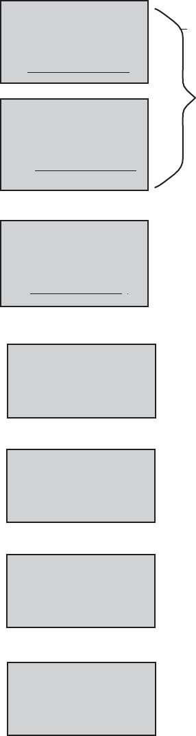
E2 Series Controller Operation Manual
24
5.2.14 User Sensors
This screen appears only if the unit is configured with additional user specified
sensors. It displays the current values read by sensor 1 (line 1) and sensor 2 (line
2). Beneath the sensor values are the units of measure assigned for each sensor.
An additional “User Sensors” screen will appear if the controller is configured to
use a 3rd or 4th user sensor. The user sensors are for monitoring purposes and
will initiate a Customer alarm upon sensor failure.
5.2.15 KVA Display
If the unit is equipped with a KVA meter, the current and KVA values for each phase
is displayed. The second and third phases are displayed only if the unit has three
phase power.
5.2.16 Differential Water Pressure
If the unit is equipped with water pressure sensors on the entering and leaving
water ports, the pressures of each are displayed and the difference between the
two is displayed.
5.2.17 Air Flow Rate
If the unit is equipped with an airflow meter, the airflow rate is displayed.
5.2.18 Water Flow Rate
If the unit is equipped with a water flow meter, the water flow rate is displayed.
5.2.19 Atmospheric Pressure
If the special sensors are enabled and Airflow Rate (No GPM) is selected in
Factory>Options>Enb Special Sensors, this screen appears displaying the source
selected in Factory>Options>BAROMETRIC PRESSURE (From Elevation, Manual,
Barometer, or Network) which is shown on the next to last line. The value of the
source is displayed on the second line and the unit of measure is either mbar or iwg.
If the source is elevation, the bottom line shows the altitude.
User Sensors 1,2
75.8
27.3
Sensor 1 Units °F
Sensor 2 Units %
KVA Display
1st Phase 23.6 amps
1st Phase 10.8 KVA
2nd Phase 23.6 amps
2nd Phase 10.8 KVA
3rd Phase 23.6 amps
3rd Phase 10.8 KVA
ATMOSPHERIC PRESSURE
16.7 IWG
Source:
From Elevation
00000Ft
WATER FLOW RATE
40.3 GPM
AIR FLOW RATE
640 CFM
Diff. Water Pressure
Entering 45.3psi
Leaving 32.6psi
Differential 12.7psi
User Sensors 3,4
75.8
27.3
Sensor 3 Units °F
Sensor 4 Units %

25
E2
Series Controller Operation Manual
5.2.20 Dual Power
If the controller is programmed to monitor dual power operation, a display screen is
provided which indicates the status of the power sources. The screen message
“OK” indicates the controller senses that both sources of power are available.
5.2.20.1
Dual Power with UPS
If the controller is programmed to manage the dual power auto transfer sequence,
a display screen is provided which indicates the programmed delay periods for the
auto power transfer sequence to begin. This screen also indicates which power
source is currently operating the unit. The status of the power sources appears at
the bottom of the display. The On/Off status of the control output signals to the
switching relays also appears.
5.2.20.2
Special Dual Power
An alternate menu may be selected in Factory>Options>Misc. Config. The only
difference is the text displayed: Preferred or Alternate instead of A or B. Otherwise,
the values are one for one to5.2.21.1.
Dual Power
Delay Pre to Alt 10s
Delay Alt to Pre 10s
Primary Preferred
Select switch at
Pre In OK Pre Out On
Alt In Err Alt Out Off
Dual Power
A/Preferred Power OK
B/Alternate Power OK
Dual Power
Delay A to B 10s
Delay B to A 10s
Primary A
A_In OK
A_Out
On
B_In OK
B_Out
Off
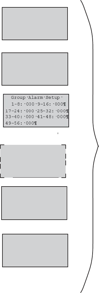
E2 Series Controller Operation Manual
26
5.2.21 Group Information Menu Screens
The Group Information menu screens only appear if the controller is set up to
operate multiple A/C unit work group. See Section 7.2.6 for a detailed description
of these screens.
Group Sensor Status
Unit 1 13 Lead Unit 2
Unit1 13 Unit5 0
Unit2
0
Unit6
0
Unit3
0
Unit7
0
Unit4
0
Unit8
0
Net T/H Sensors
00.0°F
00.0%rh
T/H Sensor Value
Local Unit 0 of 0
Network
Under
fl
oor
Static
Pr
43.6 miwg
All units off
SP Sensor Value Lead
Unit 1 of 3 Lead:2
Group
All Units Off
Avg 43.6 miwg
Min 40.4 miwg
Max 45.5 miwg
Min Static Unit 2
Max Static Unit 7
Min Hum 0
Max Temp 0 Max Hum 0
Min Temp 0
Group T/H Sensors
Avg 000.0 °F 000.0 %
Min 000.0 °F 000.0 %
Max 000.0 °F 000.0 %

27
E2
Series Controller Operation Manual
5.2.22 Modbus Fan Data
If the unit is equipped with Modbus controlled fans, the wattage being used by each
fan is displayed along with a total kW usage. Only those fans that are configured to
be present will appear on this menu.
5.2.23 Power Meter Data
If the unit is equipped with Modbus controlled fans, the wattage being used by each
fan is displayed along with a total kW usage. Only those fans that are configured to
be present will appear on this menu.
5.2.24 Electronic Expansion Valve (EEV) Status
If EEV valve(s) are used (for compressor-based systems), this screen displays
current operating parameters. The current superheat temperature, suction pressure
and suction temperature are shown. The proportional output control signal to the
valve is also shown. If the system has more than one compressor circuit, a similar
display screen is provided for each circuit.
5.2.25 CW Valve Feedback
Proportional valve actuators provide a 0-10 VDC feedback signal to confirm the
valve’s travel position. The is available as an output from the valve actuator. A value
of 100% indicates the valve is 100% open. A value of 000.0% indicates the valve
is 0% open (or closed). If the system has more than one CW valve, a similar display
screen is provided for each valve.
5.2.26 Software Version/Date
Displays the type of A/C system the controller is configured for (CW, AHU, AR), the
STULZ software version and its release date.
E2C V: 3.24
7/22/15
--- 0000.0----
EEV: 0000.0----
000%
0000stp
EVD n
o
00
SH:000-0-K
5.0
002
90P0FVA.
59.9
L3
H7e4r5t0z:W
5.6
12
5.5
Current (A)
L1 L2
L3
466.1
463.5 459.2
Line Voltage
L1 L2
CW Valve 1 Feedback
000.0%
Fan Data - Watts
#1: 120 #6: 113
#2: 133 #7 122
#3: 133 #8 119
#4: 133 #9 125
#5: 133 #10 130
Total Power: 0.0kW
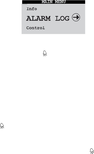
E2 Series Controller Operation Manual
28
5.3 Alarm Log
No password is required to view alarm display messages. If an
alarm condition occurs, the first active alarm may be displayed
by pressing the Alarm ) key. The alarm screen display text
message will remain unchanged until the alarm condition is
cleared. Once the alarms log is entered, any other active alarm
message(s) may be viewed by using the Up and Down arrow
keys to scroll through alarm messages.
5.3.1 Alarms
The red LED backlight within the alarm key will illuminate any
time an alarm condition is present or previous alarms existed
without having been reset or cleared. An audible alarm will also
activate when an alarm condition occurs. The audible alarm
may be enabled or disabled in the Service>Options menu. The
first active alarm screen may be displayed by pressing the
Alarm ( ) key.
The Alarm display provides a text message describing the
abnormal operating condition. Use the Up and Down arrow
keys to scroll for any additional alarm messages. Only active
alarm screens will be displayed when the Alarm ) key is
pressed. The alarm screen display will remain unchanged until
the alarm condition is corrected and the alarm key is pressed
Non-Critical Alarms
A Non-Critical alarm will activate the alarm screen
with which it is associated. These alarms are
to clear the alarm.
The alarms log may be cleared in the Service>Alarm log menu.
The application software supports two (2) types of alarms:
Non-Critical and Critical. Any alarm may be programmed to
activate the user configured Custom alarm relay contacts.
programmed to activate the Summary Fault alarm and close the
Summary Fault relay contacts without stopping unit operation.
Some examples of the factory programmed, Non-Critical alarms
are:
High Temperature
High Airflow
Low Temperature
Dirty Filter
High Humidity
Sensor Failure
Low Humidity
Communication Failure
Leak Detection
Condensate Pan Full
Low Airflow(Velocity Sensor)
CW Flow Failure
5.3.3 Critical Alarms
Critical Alarms will coincide with automatic shutdown of the A/C
unit(s) equipment as needed to prevent possible system
damage. The A/C unit(s) equipment will remain shut down until
the alarm condition(s) are no longer sensed and the controller
has been reset. Some examples of Critical alarms are:
High Humidity
Low Suction Pressure
Fire/Smoke Detection
High Head Pressure
No Airflow (Air Proving Switch
Off by Internal Alarm (Only for grouped systems)

29
E2
Series Controller Operation Manual
5.3.4 Alarm Screen Messages
ALARM MESSAGE DESCRIPTION OF ALARM CONDITION
High Temperature
Temperature is above user defined alarm setpoint.
Low Temperature
Temperature is below user defined alarm setpoint.
High Humidity
Humidity is above user defined alarm setpoint
Low Humidity
Humidity is below user defined alarm setpoint.
Sensor Failure
Sensor is disconnected or faulty.
Communication Failure
External and/or internal communication lost (BMS or pLAN)
Condensate Pan Full Water level in condensate pan is reaching an unsafe level.
Water Water leak sensed by leak detector.
High Airflow Air velocity is above user defined setpoint.
Low Airflow Air velocity is below user defined setpoint.

30
E2 Series Controller Operation Manual
ALARM MESSAGE DESCRIPTION OF ALARM CONDITION
No Airflow
Airflow is inadequate for detection by the air proving switch.
Filter Clogged
Filter needs to be replaced.
True No Flow
Insufficient flow of cooling fluid detected by flow switch (CW/WG
units).
No Flow Water Temp
Insufficient flow of cooling fluid detected by temperature sensors
(CW/WG units).
Smoke/Fire
An alarm condition detected by the smoke detector or firestat.
High Head Pressure
Head Pressure is above user configured alarm threshold (DX units).
Low Suction Pressure
Suction Pressure is below user configured alarm threshold (DX
units).
Fan 1, 2, 3, 4, ...10
Fan Failure.
pCOe Disconnected
No communications with the controller.
pCOe Mismatch Alarm
No output pattern confirmation for more than 10 seconds.
Customer Alarm Customer supplied signal indicates an alarm.
Heater Failed The heater has an over temp or other condition.
Pump The pump has failed due to overcurrent or other conditions.
Power Source Lost The indicated power source is not present.
Humidifier An alarm in the humidifier is present.
Blower Failure The indicated blower has failed to run.
Damper End Switch The damper end switch failed.
Fan Lockout The fan has failed too many times and is locked out.
EVD offline The Expansion Valve controller is offline.
Ebmpapst Fan#_- Fan Fault The indicated alarm has been received from the fan.
Ebmpapst Fan#_- Device Offline The indicated alarm has been received from the fan.
Ebmpapst Fan#_- Phase Fault The indicated alarm has been received from the fan.
Ebmpapst Fan#_- Motor Blocked The indicated alarm has been received from the fan.
Ebmpapst Fan#_- Mains Under Voltage
The indicated alarm has been received from the fan.
Ebmpapst Fan#_- Mains Over Voltage
The indicated alarm has been received from the fan.
Ebmpapst Fan#_- DC Link Over Voltage
The indicated alarm has been received from the fan.
Ebmpapst Fan#_- DC Link Under
Voltage
The indicated alarm has been received from the fan.
Ebmpapst Fan#_- Motor Superheating
The indicated overheat alarm has been received from the fan.
Ebmpapst Fan#_- Intern. Circ.
Superheat
The indicated overheat alarm has been received from the fan.
Ebmpapst Fan#_- Output Stage
Superheat
The indicated overheat alarm has been received from the fan.
Ebmpapst Fan#_- Hall Sensor Error The indicated alarm has been received from the fan.

31
E2
Series Controller Operation Manual
ALARM MESSAGE DESCRIPTION OF ALARM CONDITION
Ebmpapst Fan#_- Communication Error
The indicated alarm has been received from the fan.
Ebmpapst Fan#_- Generic Error The indicated alarm has been received from the fan.
Ebmpapst Fan#_- Out Stage High Temp.
The indicated warning has been received from the fan.
Ebmpapst Fan#_- Intern. Circ. High Temp.
The indicated warning has been received from the fan.
Ebmpapst Fan#_- Motor High Temperature
The indicated warning has been received from the fan.
Ebmpapst Fan#_- DC Link Voltage Low
The indicated warning has been received from the fan.
Ebmpapst Fan#_- Limited Mains Power
The indicated warning has been received from the fan.
Ebmpapst Fan#_- Limited Mains Current
The indicated warning has been received from the fan.
Ebmpapst Fan#_- Brake mode The indicated warning has been received from the fan.

32
E2 Series Controller Operation Manual
5.3.5 Control Menu
From the Control Menu the operator may select from four sub-menus:
Setpoints, Alarm Setpoints, Clock and Version. The controller is programmed
to require level 1 password authorization to enter this menu (see Section 3.2.1).
Once password access is granted, the setpoints controlling the performance
of the unit may be selected and adjusted, alarms may be enabled, alarm
setpoints may be entered and the clock may be set to establish an operating
schedule for the A/C unit.
The Setpoints (SET) screens allow the operator to view and adjust the
temperature and humidity setpoint control parameters and compare them to
system level operating data derived from the various Sensor/Transmitter
inputs. See Section 5.4.1.
The Alarm Setpoints (ALARM SET) screens allow the operator to enable
and adjust the high and low temperature and humidity alarm setpoints and
offsets and compare them to the control setpoints and to the system level
operating data derived from the Sensor/Transmitter inputs. See Section
5.4.2.
The Clock screens allow the operator to view and adjust the current time,
date and day and set-up operating schedule(s) and setpoints for the A/C
system. See Section 5.4.3
Two Version screens are provided for information only. They show controller
hardware and software details that are useful to STULZ Product Support if
technical assistance is needed.
pCO type: pCO3 Large
Ram: 512KB
Built-In type: None
Main cycle:
3.9 cycles/s 265ms
Information
CONTROL
Clock
VERSION
Set
Information
E2C Application Code:
Ver.: 03.24 07/22/15
Carel S.p.A. code:
Bios: 6.31 11/04/14
Boot: 4.03 07/03/06
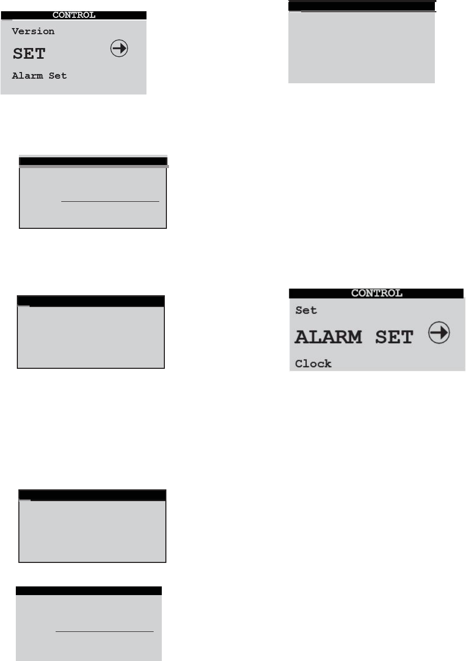
33
E2
Series Controller Operation Manual
5.4.1 Setpoint Screens
5.4.1.2 Max GPM
The Setpoints (SET) screens below may be accessed from the
Control menu.
Temperature
Set Point 72.0°F
STATUS
Temp: 72.6°F Set:72.0°F
Dew: 50.1°F
If the customer sensor(s) are set for Calculate GPM in
Factory>Options>Enb Special Sensors, then the GPM menus
for CW circuit 1 and 2 (if appropriate) are enabled. The maximum
GPM is used to limit the CW valve opening. The current GPM is
the calculated GPM. Del T1 Flow ON is the number of degrees
below the leaving water temperature that the entering water
temperature must be to enable GPM calculations. Del T1 Flow
OFF is the number of degrees below the leaving water
temperature that the entering water temperature must be to
disable GPM calculations. The bottom field in the screen (Valve)
is the current position of the valve as a percentage of fully
open.
5.4.2 Alarm Setpoint Screens
The Temperature and Humidity setpoint screens allow the
operator view and adjust the control setpoints and compare
them to system level operating data derived from the various
Sensor/Transmitter inputs.
5.4.1.1 High Pressure Auto Reset (Optional)
The Alarm Setpoints screens are accessed from the Control menu.
They allow the operator to enable the High and Low temperature
and humidity alarms, adjust their setpoints and compare them to the
control operating setpoints and to the system level operating data
derived from the Sensor/ Transmitter inputs.
Set:45%
45.5°F
50.1°F
Hum:
Dew:
STATUS
45.0%
Set Point
Humidity
375psi
200psi
HP Limit:
HP Rst Min:
High Pressure Limit
Temperature Alarm
Low alarm Enable:Yes
Set Point 60.0°F
STATUS
Tem
p: 72.6°F Set:72.0°F
Dew: 50.1°F
Max GPM: 40.0
Current GPM: 23.4
Del T1 Flow On: 1.5
Del T1 Flow Off: 2.0
Valve: 45.5%
CW1 Max GPM
34
E2 Series Controller Operation Manual
If the compressor discharge pressure rises to the limit
value entered, the compressor turns off.
After the compressor minimum off time delay expires,
the controller polls the discharge pressure sensor to
determine if it is safe to start again. If the pressure is
below the high pressure reset minimum (HP Rst Min)
value entered, the compressor restarts.
If the discharge pressure is not below the high pressure
reset minimum value, the compressor remains off.
The controller polls the sensor a total of three times to
attempt to start the compressor, each time following
the compressor minimum off time delay period. If the
discharge pressure is still not below the high pressure
reset minimum value after three attempts, the
compressor is disabled and a high-pressure alarm is
signaled.
This is a critical alarm requiring the controller to be
manually reset by pressing the alarm key on the user
interface display panel.
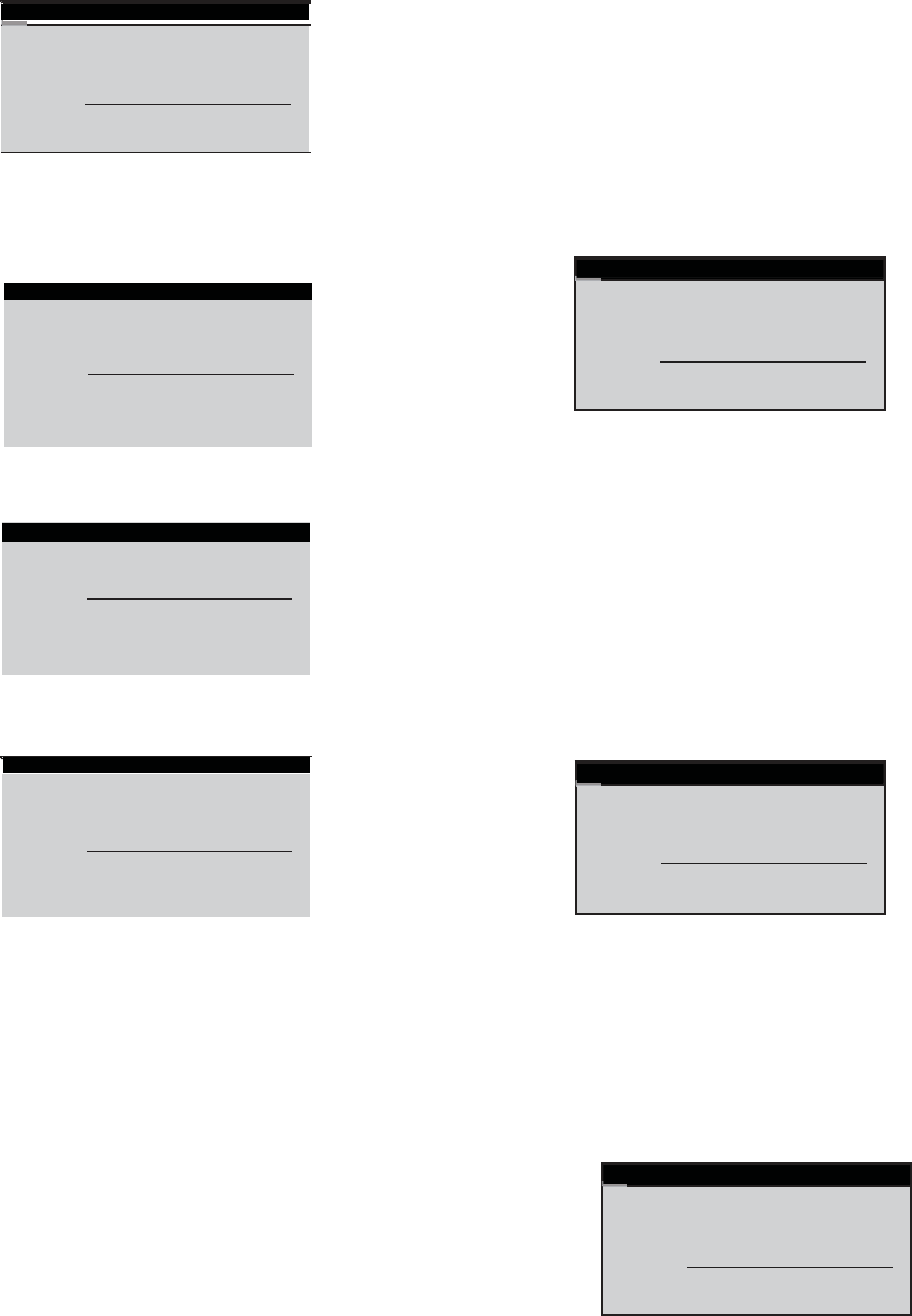
35
E2
Series Controller Operation Manual
High alarm Enable:
Yes
Set Point 70.0%
STATUS
Hum: 45.6% Set:45.0%
Dew: 50.1°F
High Humidity
Alarm
The High Temperature Alarm will cancel at 75 °F.
Conversely, the low temperature alarm will cancel when the
actual temperature rises to the LowTemperature Alarm setpoint
(60.0 °F) + the Offset (5.0 °F), or, 60.0 °F + 5.0 °F = 65.0 °F.
The Low Temperature Alarm will cancel at 65.0 °F.
EXAMPLE 2: Humidity Alarm Offset
Low Humidity Alarm
High Water Temperature Alarm
Low Water Temperature Alarm
Following the temperature and humidity alarm enable screens
are the alarm offset screens. From these screens the operator
may adjust offsets for the high and low alarm setpoints at
which the alarm will be cancelled. The entered offset applies
to both the upper and lower values entered in the Alarm
Setpoints Screens. The offset is subtracted when its applied
to the high alarm setpoint and it is added when its applied to
the low alarm setpoint.
EXAMPLE 1: Temperature Alarm
Offset
If the offset for the humidity alarm is set at 5% (default), the high
humidity alarm will cancel when the actual humidity drops to
the High Humidity Alarm setpoint (70.0%) - the Offset (5.0%),
or, 70.0% - 5.0% = 65.0%
The High Humidity Alarm will cancel at 65%.
Conversely, with the default offset at 5.0%, the Low Humidity
Alarm will cancel at 35%. (Setpoint 30.0% + Offset 5.0%))
30.0% + 5.0% = 35.0%
EXAMPLE 3: Water Temp Alarm Offset
If the offset for the water temperature alarm is set at 5 °F
(default), the high water temperature alarm will cancel when the
actual temperature drops to the High Water Temperature Alarm
setpoint (60.0 °F) - the Offset (5.0 °F), or, 60.0 °F - 5.0 °F =
55.0 °F. The high water temperature Alarm will cancel at 55
°F.
If the offset for the temperature alarm is set at 5.0 °F (default),
the high temperature alarm will cancel when the actual
temperature drops to the High Temperature Alarm setpoint
(80.0 °F) - the Offset (5.0 °F) or, 80.0 °F - 5.0 °F = 75.0 °F
Low alarm Enable:Yes
Set Point 30.0%
STATUS
EWT1 Temp: 54.0°F
EWT2 Temp: 59.0°F
STATUS
Temp: 72.6°F Set:72.0°F
Dew: 50.1°F
5.0%
Offset:
Humidity Alarm
High alarm Enable:Yes
Set Point: 60.0
STATUS
EWT1 Temp: 54.0°F
EWT2 Temp: 59.0°F
Low alarm Enable:Yes
Set Point: 40.0
STATUS
EWT1 Temp: 54.0°F
EWT2 Temp: 59.0°F
STATUS
EWT1
Temp: 54.0°F
EWT2 Temp: 59.0°F
5.0°F
Offset:
Water Temp Alarm
Water Temp Alarm
STATUS
Temp: 72.6°F Set:72.0°F
Dew: 50.1°F
5.0°F
Offset:
Temperature Alarm
Water Temp Alarm
Humidity Alarm
Humidity Alarm
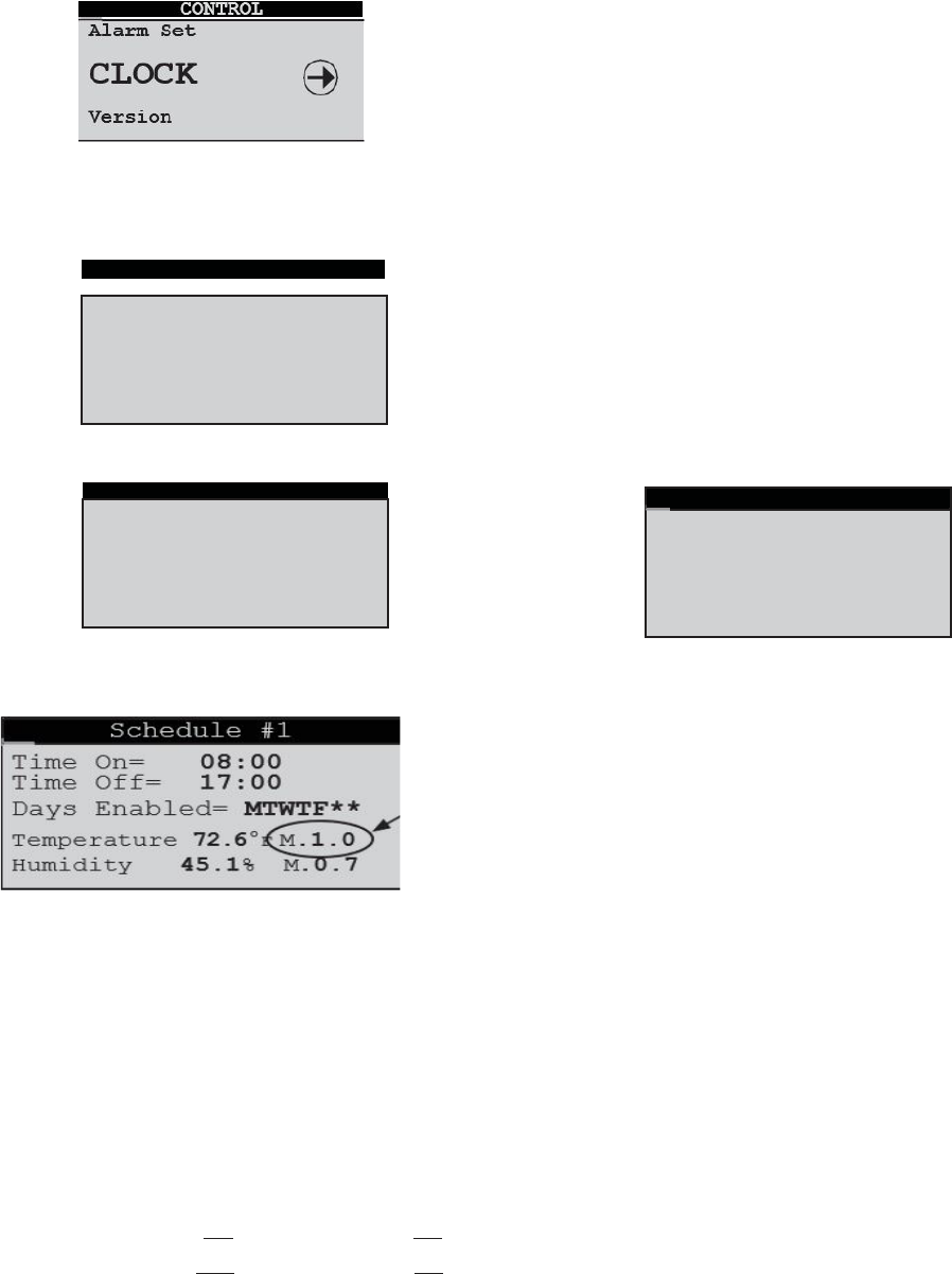
36
E2 Series Controller Operation Manual
5.4.3 Clock Screens
The Clock screens may be accessed from the Control menu.
From these screens the operator may set the time, date and
day and may choose to set-up an operating schedule for the
A/C system.
The Set Clock screen allows the operator to set and/or adjust the
current time, date and day.
Set Schedules
Consult the manual
before programming
schedules.
Number Schedules:
2
The Set Schedules screen allows up to seven operating
schedules to be enabled.
As an example, the above schedule may be set for normal
workday operations with selected on/off times (ex. 8:00 AM to
5:00 PM) and with the temperature set at 72.6 °F and humidity
set at 45.1%. The M value adjacent to the entered setpoint
parameter is for applying a multiplier to scale both the cut-in
and cut-out offsets.
The multipliers are factored to the system offset values set in
the Service menu (see Sections 5.5.1, 5.5.2 and 5.5.3), only for
the schedule time period being set.
Default Cut-in/Cut-out Offsets
Temp. Cut-in Offset= 2.0 °F; Cut-out Offset= 0.3 °F
Humidity Cut-in Offset= -5.0%; Cut-out Offset= -2.0%
EXAMPLE 1: Temperature Offset Multiplier
With the default cut-in offset for temperature at 2 °F, a multiplier
of M.1.0 × 2 °F= 2 °F. This means the unit will begin operating
in the cooling mode at 74.6 °F (Setpoint 72.6 °F + Offset 2 °F).
Conversely, with the default cut-out offset at 0.3 °F, the
cooling mode will turn off at
72.9 °F. (Setpoint 72.6 °F + (M.1.0 × Cut-out Offset 0.3 °F))
72.6 °F + 0.3 °F = 72.9 °F.
EXAMPLE 2: Temperature Offset Multiplier
If M.2.0 is entered, the off set for temperature is multiplied by2.0.
(M.2.0 × 2 °F= 4 °F). This means the unit will begin operating
in the cooling mode at 76.6 °F (Setpoint 72.6 °F + Offset 4 °F).
Conversely, the cooling mode will turn off at 73.2 °F (Setpoint
72.6 °F + (M.2.0 × Cut-out Offset 0.3 °F)).
EXAMPLE 3: Humidity Offset Multiplier
With the default cut-in offset for humidity at -5%, a multiplier
of M.0.7 × -5% = -3.5%. This means the humidifier will begin
operating at 41.6% RH (Setpoint 45.1% + Offset -3.5%).
Conversely, with the default cut-out offset at -2% the
humidification mode will turn off at 43.7%RH.
From the Schedule #1 screen, press the up or down arrow keys
to access additional enabled schedules (2-7).
Schedule number 2 may be set with higher temperature
and humidity setpoints for scaling back operation during the
evening hours (night setback).
In these examples the unit is scheduled to not operate at all
on Saturday and Sunday. Those days may be added to
schedules 1 and 2 or a separate schedule may be set up for
weekend operation if different temperature and humidity
setpoints are preferred.
Set Clock
47.0% M.0.5
Days Enabled= MTWTF**
Temperature
74.0°F M.
1.0
Humidity
07:59
17:01
Time Off=
Time On=
Schedule #2
Time: 00:00
Date: 00/00/0000
Day: XXXXXXX
Offset
Multiplier
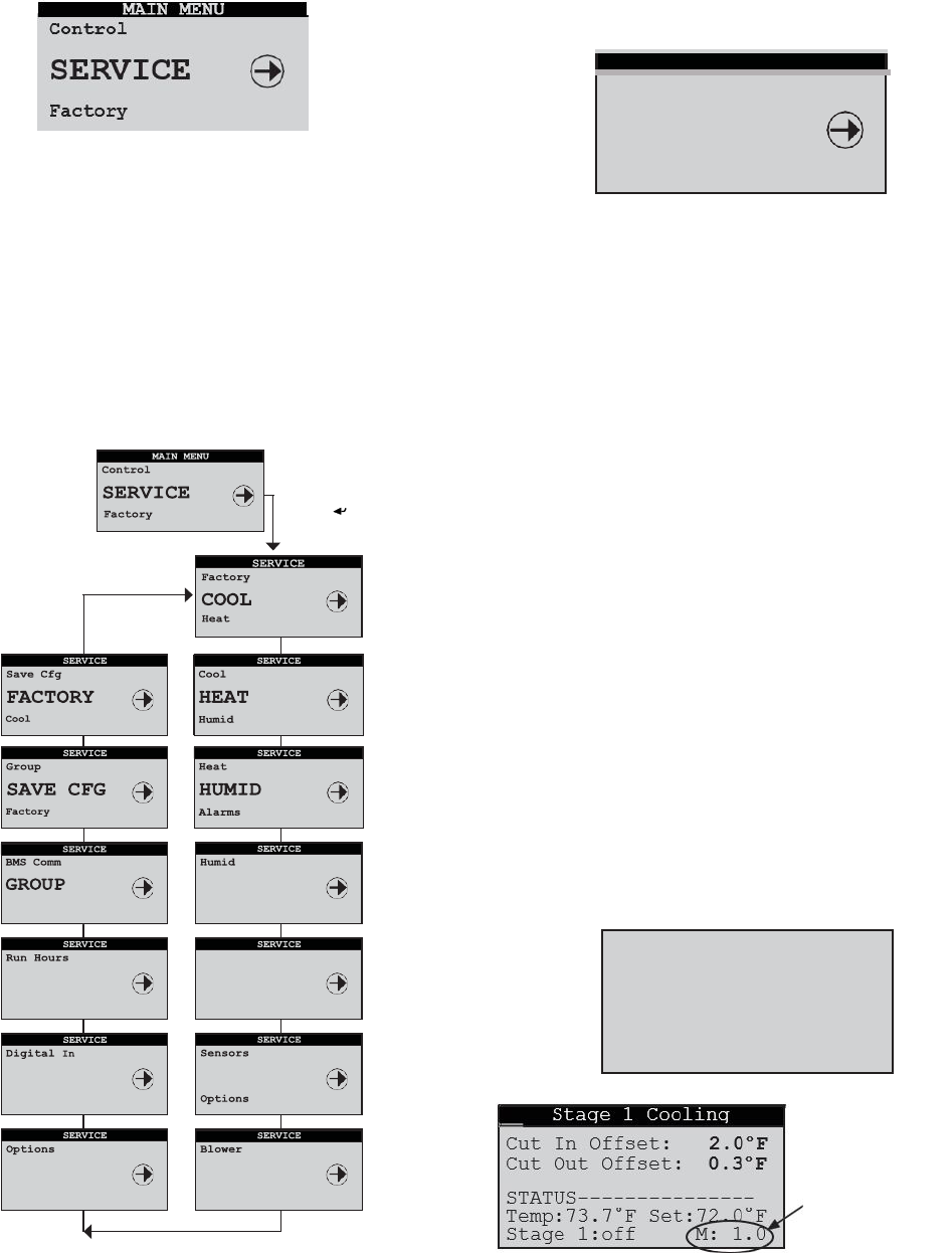
37
E2
Series Controller Operation Manual
5.5 Service Menu
The Service menu screens allow the user to enter cut-in and
cut-outvalues, calibrate the system control sensor(s), save
and restore parameters and view the event log. The Service
menu may be entered and programmed by the user via the
password menu (requires level 2 password). Once password
access is granted, the user may access the service menu
screens.
It allows the operator to adjust the number of days for
switching the lead cooling circuit duty and select an hour of
the day for this to occur. The current lead circuit may also
be changed at the display
Figure 8. Service Menu Selections
5.5.1 Cool
The Service>Cool menu screens differ depending upon
whether the A/C unit is configured
for DX operation and/or
CW/WG/AWS operation.
5.5.1.1
DX Cooling Screens
If the A/C unit has compressor(s), the cut-in/ cut-out
offsets for each compressor stage may be adjusted from
the Service>Cool menu. The offset values are added to the
temperature setpoint and establish the temperatures for the
compressor to turn on (Cut-in) and off (Cut-out). This screen
displays the current air temperature and setpoint
temperature. The On/Off status of the compressor (Stage 1)
is shown along with the offset multiplier (M). The offset
multipliers may be set in the Service>Options>T/H Scaling
menu screen
If the A/C unit is configured for operation as a dual
compressor or tandem compressor system, additional
screens are provided for viewing and adjusting parameters
for the additional stages. Ordinarily, A/C units equipped
with multiple compressors stage the operation of the
compressors based on rising air temperature. The
compressors rotate after each run cycle.
A Redundant Set-up screen appears next for units
equipped with dual compressors (STULZ models VFS and
CFS), if the unit is configured for redundant operation.
SERVICE
Blowers
COOL
Heat
Redundant Setup
Number of Days 0
Hour of Day 0
Current Lead 1
Press Enter ( )
Key
ALARMS
Save Cfg
Sensors
BMS COMM
Group
Alarms
SENSORS
Blower
RUN HOURS
BMS Comm
BLOWER
Digital In OPTIONS
Run Hours
Digital In
Offset
Multiplier
38
E2 Series Controller Operation Manual
5.5.1.2
CW Cooling Screens
Offset Multiplier
See Sect. 5.5.7.3
If the A/C unit is configured for CW, AWS or FC operation, the
cooling band may be adjusted in the Service>Cool menu. The
Cooling Band establishes the number of degrees above
setpoint (+ the CW Cut In/Out value described below) for
the valve to reach the fully open position.
The Min delta
T1 is the minimum temperature rise expected
between the entering and leaving water temperature. A flow
alarm is activated if the temperature difference falls below
this value while the unit is actively cooling. The CW Cut In/
Out value is the offset added to the temperature setpoint and
establishes the temperatures for the control valve to open (Cut-
in) and close (Cut-out) as well as the P/I dead band.
This screen also displays the current air temperature and
setpoint temperature. The position of the flow control valve is
shown at the bottom of the screen along with the offset
multiplier. If the A/C unit is configured for operation as a dual
CW system, a second screen is provided for viewing and
adjusting parameters for the second cooling circuit (CW2).
The Redundant Set-up screen appears next if a dual CW unit
is configured for redundant operation (see Section 5.5.1.1).
The A/C unit is equipped with an optional valve selector switch
on the front door, a field appears in the bottom of the screen
that allows it to be enabled. When enabled, the valve switch
takes priority over the entries in the display.
5.5.2 Heat
The cut-in/cut-out offsets for each heating stage (up to three
stages) may be adjusted from the Service>Heat menu.
5.5.3 Humidity
The cut-in/cut-out offsets for the Humidify, Dehumidify and
Reheat modes may be adjusted from the Service>Humid menu.
NOTE: The Humidifier screen only appears if the A/C unit is
equipped with a humidifier at the factory.
SERVICE
Heat
HUMID
Alarms
Humidi
fi
er
Cut In Offset: -5.0%
Cut Out Offset: -2.0%
STATUS---------------
Hum: 43.1% Set:45.0%
Hum:Off M: 1.0
Dehumidify
Cut In Offset: 5.0% Cut
Out Offset: 2.0%
Cutout Temp: -4.0°F
STATUS---------------
Hum: 43.1% Set:45.0%
Dehum:Off M: 1.0
Dehumidify OA Unit
2nd DX Cut In: 10.0%
2nd DX Cut Out: 5.0%
STATUS---------------
Hum: 43.1% Set:45.0%
Dehum:Off M: 1.0
The following screen is provided for CW/ AWS or FC based
units only.
Redundant Setup
Number of Days 0
Hour of Day 0
Current Lead 1
Valve:0.0% M: 1.0
STATUS---------------
Temp:73.7°F Set:72.0°F
3.0°F
2.0°F
CW Cut In/Out:
Cooling Band:
Min deltaT1:
CW, AWS, FC
Ht1:Off M: 1.0
STATUS---------------
Temp:73.7°F Set:72.0°F
-2.0°F
Cut Out Offset: -0.3°F
Cut In Offset:
Heat Stage 1
SERVICE
Cool
HEAT
Humid
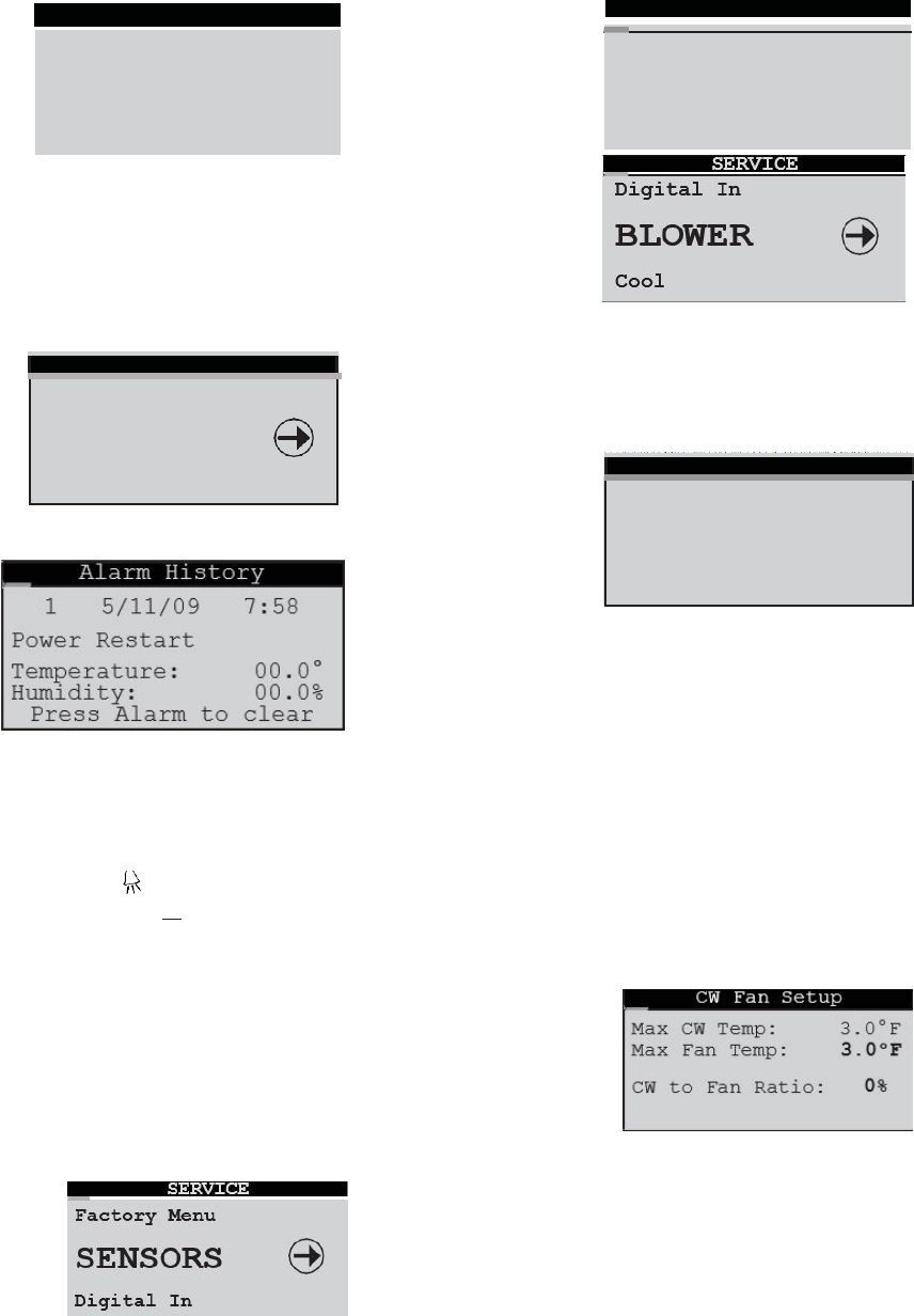
39
E2
Series Controller Operation Manual
The maximum position to open the CW valve, while in the
dehumidification mode, may set. This may be used when the
heat load is low to reduce possible setpoint temperature
overshoot while the unit is dehumidifying the air in the CW,
AWS or FC mode.
5.5.4 Alarms
SERVICE
Humid
ALARMS
BMS Comm
Sensors Offset screen (example).
A log of events is stored for view from the Service>Alarms
menu. This menu displays the last 50 events sequentially
numbered in order of occurrence. The alarm log is cleared by
pressing the Alarm key while in this menu.
If the Alarm ) key is pressed when in any of the
Service>Alarms screens, all stored alarm messages will be
permanently erased from the controller's memory.
5.5.5 Sensors
When calibrating sensors, an offset at one
extreme may produce an error at the other
extreme. Always verify that any offset is valid over
the entire range of the sensor.
5.5.6 Blower
From the Service>Blower menu, screens may be accessed to view
and adjust the blower speeds, set the CW to Fan ratio and set-up the
underfloor static pressure if applicable.
5.5.6.1
Blower Set-up
The fan runs at the low speed setting whenever there isn't call
for heating, cooling, dehumidification or humidification. The
fan speed increases directly to the run speed during heating or
ramps up to that speed during cooling or humidification based
on the air temperature (see next Section 5.5.6.2). The fan
speed during dehumidification can be controlled in conjunction
with the CW valve opening to limit the potential for over-cooling
(see CW Valve Dehum screen in Section 5.5.3).
The lower field (Water Alarm Action) maybe used to set the
action of the blower(s) in response to a CWorWG flow alarm
condition. The selections are None, Off, Min(speed)or Max(speed).
5.5.6.2
CW Fan Set-up
From the Service>Sensors menu, multiple display screens may
be accessed to enter offsets for calibrating the unit's various
sensors.
This screen is provided for CW based units. The max CW
temperature is the offset above the temperature setpoint
Sensor Offsets
Valve% in dehum
100.0%
Return Air Temperature
Apply Offset: 0.0°F
Displayed: 72.3°F
CW Valve Dehum
Blower Setup
Run Speed 100%
Low Speed 60% Dehum
Fan Speed: 60% Water
Alarm Action: None
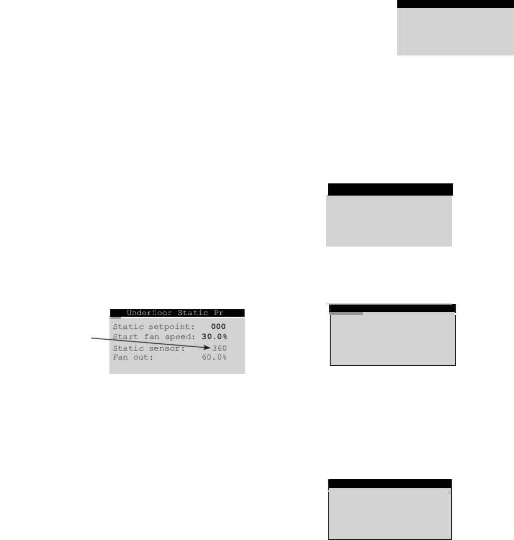
40
E2 Series Controller Operation Manual
at which the CW valve is fully open, or 100%. The max fan
temperature is the offset at which the fan speed reaches the
Run Speed value (typically 100%). At the default values of 3
degrees each, the CW valve position will be 50% open at 1.5
degrees above setpoint and the fan speed will be 85%, as in
halfway between 70% and 100%.
The CW to Fan ratio is to be used as a method of tuning in the
interaction of the fan and CW valve after the temperature offsets
are determined. A positive ratio value between 0% and 25%
increases the CW valve position by that amount while decreasing
the fan speed by the same amount. A negative value decreases
the CW valve position while increasing the fan speed.
For the setting of above 50% CW valve and 85% fan speed, a
10% ratio will increase the CW valve to 55% and decrease the
fan speed to 76.5%. A -10% ratio will decrease the CW valve to
45% while increasing the fan to 93.5%. The regular limits on the
CW valve and fan still apply. If the unit is in the dehumidification
mode, the fan speed will be limited to the Dehum Fan Speed
parameter.
5.5.6.3
Static Pressure Set-up
On units equipped for static pressure control, static pressure
should be set-up and enabled when commissioning the A/C
unit. The operating static pressure can only be set correctly
after the A/C unit is installed and operable in its intended
location.
To set the static pressure, turn on the A/C unit and allow the
blower(s) to reach full speed. Then, call up the Service menu.
Enter the Service level password and scroll to the
Blower>Underfloor Static Prg screen. This screen is only
available when the controller is configured by the factory to
Next, scroll up
to the Service>Blower>Blower
Setup screen (See Section 5.5.6.1). Adjust the Low Speed
value up or down accordingly to raise or lower the current
static pressure. Return to the Service> Blower>Underfloor
Static Pr screen and observe the resultant Static sensor value.
The static pressure is the square of the fan speed. A small
change in fan speed will have a large effect on the underfloor
static pressure.
It will be necessary to fine tune the static pressure by
repeating the steps of setting the Low Speed
value in the Service>Blower>Blower Setup screen
and then checking the static pressure result in the
Service>Blower>Underfloor Static Pr screen. When the
adjusted Low speed value produces the desired static pressure,
write down both the Low Speed value
Re-enter the Service menu and scroll to the
Service>Blower>Underfloor
Static Pr screen. Enter the
Static setpointvalue
that appeared in the
Static sensor field
and enter the Start fan
speed value that
was the final Low Speed value.
The A/C unit will now operate using proportional control to
maintain the static pressure at the setpoint entered.
If the speed values are adjusted in the Service>Blower Setup
screen (Section 5.5.6.1), it will have no effect on the operating
fan speeds as they are now controlled by static pressure.
5.5.6.4
Modbus Fan Control and Data
Monitoring
This screen appears if the controller is configured for Modbus
fan control with a Field bus expansion card. It allows
adjustments to fan kW limiting parameters. Limits total kW of
all fans (sum). P/I control parameters may also be adjusted.
Fan
Data
- Watts #1
#1
#2
#3
#4
#5
Power
Total
0
0
0
0
0
Add:
Power:
#6
0
#7
0
#8
0
#9
0
#10
0
0
0.0kW
Modbus Data – Watts
The real time power consumption in kW is displayed for each fan. It
may be used to estimate the total power consumption for the
system while it operates. First enter a Power Add value which will
be added to the real time power consumption of both fans. The
Power Add value is the estimated sum (in watts) for the balance
of the system loads. I.e. power transformer, etc. The result is
displayed in the lower field Total Power:
Fan
Data
-
RPM
#1
0
#6
0
#2
0
#7
0
#3
0
#8
0
#4
0
#9
0
#5
0
#10
0
Fan Total: 0.0kW
Fan Avg: 0.0kW
PID Output: 0.0%
Limit Fan kW: No
Fan
Totl Limit: 0.0
kW
Prop:200 Int: 10
Err db: 4 Action:Rev
Fan kW Limiting
Static setpoint:
360
Start fan speed: 60.0%
Static sensor: 0
Fan out: 00.0%
Under
fl
oor
Static
Pr
Make note of the
current miwg
static
pressure value
shown in the display
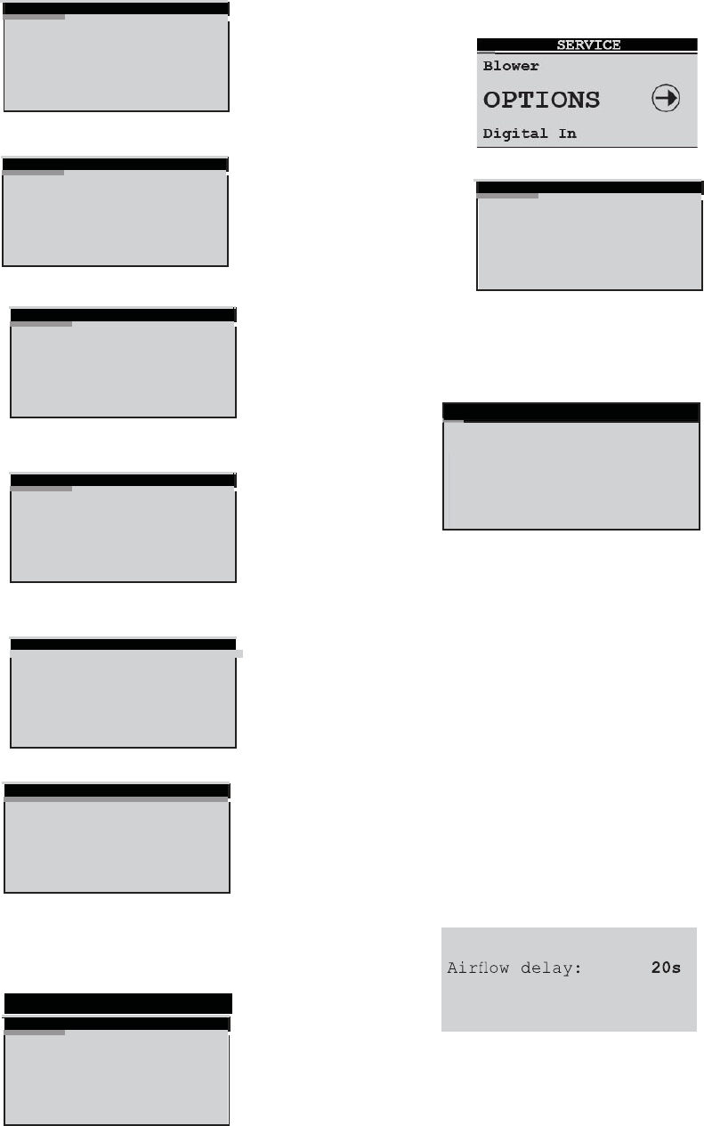
41
E2
Series Controller Operation Manual
Modbus Data – Fan RPM (view only)
Additional view only Modbus fan data screens appear after
the Fan RPM data screen. These data screens provide the
following information for each fan:
Fan
Data
-
Circ.
Temp
#1
0
#6
0
#2
0
#7
0
#3
0
#8
0
#4
0
#9
0
#5
0
#10
0
Circuit Temperature, in degrees Celsius, of fan motor housing
Fan
Data
-
Hours
#1
0
#6
0
#2
0
#7
0
#3
0
#8
0
#4
0
#9
0
#5
0
#10
0
Fan Run hours
Fan
Data
-
DC
Link
V
#1
0
#6
0
#2
0
#7
0
#3
0
#8
0
#4
0
#9
0
#5
0
#10
0
DC Link Voltage (Voltage on the DC bus – not AC supply
voltage)
Fan
Data
-
DC
Link
A
#1
0
#6
0
#2
0
#7
0
#3
0
#8
0
#4
0
#9
0
#5
0
#10
0
DC Link Amperage (Amps on the DC bus – not AC supply
voltage)
Fan Data -
#1
ID
Serial #
Wk
Yr
0
00000000
00
00
#2
0
00000000
00
00
#3
0
00000000
00
00
#4
0
00000000
00
00
#5
0
00000000
00
00
Fan ID/Serial number/Week and year of build
Fan Communication
#1
0
#6
0
#2
0
#7
0
#3
0
#8
0
#4
0
#9
0
#5
0
#10
0
Status of fan communication with STULZ E² controller
Fan Max speed – Maximum allowed speed in RPM
Pulse Width Modulation (PWM) being sent to the motor.
5.5.7 Options Menu
Fan
Data-
PWM
Out
#1
0
#6
0
#2
0
#7
0
#3
0
#8
0
#4
0
#9
0
#5
0
#10
0
From the Service>Options menu, the Enter ( ) key may be
pressed to access a sub-menu with screens used to set-up and
adjust various options.
5.5.7.1
Control, Startup
The Service>Options>Control, Startup screen allows the
operator to select the control method (Standard, Dewpoint or
Hybrid).
Auto on powerup - If set to On, the A/C unit turns on
automatically when main power is applied.
Auto on remote - If set to On, the A/C unit may be turned on
via a remote On/Off switch.
EPO Option (Emergency Power Off) - If set to On, the off
delay timers are bypassed so compressors, blowers etc. stop
operating immediately when the unit is turned off by a remote
On/Off signal or a critical alarm.
Suppress Buzzer - Allows the operator to enable or disable
the alarm signal buzzer.
5.5.7.2
Unit Timers
Unit Timers
Fan
Data-
Max
Speed
#1
0
#6
0
#2
0
#7
0
#3
0
#8
0
#4
0
#9
0
#5
0
#10
0
The Service>Options>Unit Timers screen allows the operator to
adjust the unit timers controlling various start-up or shut down
delay periods.
Auto on powerup: On
Auto
on remote: On
EPO
Option:
Off
Suppress Buzzer: No
Standard
Control:
Control, Startup
5s
60s
Recovery time: 30mins
Shutdown delay:
Startup delay:
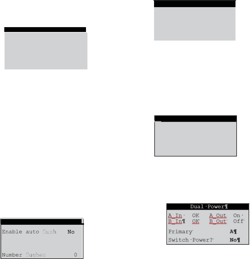
42
E2 Series Controller Operation Manual
Startup delay - Time delay before blower(s) begin
operating after pushing the Enter key or after turning the unit
on with a remote on command.
Air
fl
ow
delay
-
Time
delay
for allowing
the
blowers
to
reach
adequate speed before the air proving sensor actively monitors
an airflow alarm condition.
Shutdown delay - Time delay before unit stops operating
after pressing the Enter key for three seconds or after turning it
off with a "remote off" command.
Recovery time - Time period after startup that temperature
and humidity alarms are masked from signaling nuisance high
or low temperature and humidity alarms.
5.5.7.3
T/H Offset Scaling
valve position ever exceeds the percentage entered since the
last flush cycle, the scheduled flush cycle will be skipped and a
new interval will begin. If the valve does not reach the minimum
open position entered, aflush cycle will occur when the interval
since the last flush cycle expires. The interval between flushes
may be varied from 1 hour to 720 hours (30 days). The
duration of the flush cycle may be varied from 30 to 300
seconds. The number of flushes displayed at the bottom of
the screen is the total number of flush cycles since the A/C
unit was initialized.
5.5.7.5 Barometric Pressure
The Service>Options>T/H Offset Multiplier screen allows
the operator to enter a multiplier to apply to scale both the
temperature and humidity cut-in/cut-out offsets. The multipliers
are factored to the system offset values set in the Service menu
(Sections 5.5.1, 5.5.2 and 5.5.3).
Default Cut-in/Cut-out Offsets
Temp. Cut-in Offset= 2.0 °F; Cut-out Offset= 0.3 °F
Humidity Cut-in Offset= -5.0%; Cut-out Offset= -2.0%
EXAMPLE: Temperature Offset Multiplier
With the default cut-in offset for temperature at 2.0 °F, a
multiplier of 2.0 × 2 °F = 4 °F. This means the unit will begin
operating in the cooling mode at 76.0 °F (Setpoint 72.0 °F +
Offset 4 °F). Conversely, with the default cut-out offset at 0.3 °F,
the cooling mode will turn off at 72.6 °F.
(Setpoint 72.0 °F + (2.0 × Cut-out Offset 0.3 °F))
72.0 °F + 0.6 °F = 72.6 °F
5.5.7.4 Auto Flush Cycle
Auto Flush Cycle
For valve
Interval
Duration
under
1
0
0.0%
hrs
secs
The Service>Options/Flush Cycle screen may be
used to enable a periodic flushing of the CW, FC or
AWS coils with the control valve in the fully opened
position. This is used to remove any sediment that may
have collected while the A/C unit is actively cooling.
(This does not operate if the A/C unit is off or in
The barometric pressure set-up menu is enabled when the
special sensors are selected to be “Airflow rate (no GPM)” or
“Calculate GPM” in the Factory>Options>Enb Special Sensors
menu. Select Elevation (default), Manual, Local Sensor, or
Network. The elevation defaults to sea level (0). Manual selects a
fixed barometric pressure in millibars. Local Sensor selects an
analog input to provide the barometric pressure in millibars.
Network selects a BMS supplied value for the barometric
pressure in millibars.
5.5.7.6
Dual Power
The Service>Options>Dual Power Setup screens appear only
if the controller is programmed to manage the automatic dual
power transfer sequence. The controller uses its onboard
timers for power switch over, not the relay timers in the A/C
unit. This screen allows the delay timers for automatic dual
power switch over to be adjusted.
If enabled, a minimum valve opening threshold may be set
below which a periodic flush cycle is required. That is, if the
control
The next Service>Options>Dual Power screen allows the
status of the dual power sources to be viewed if the
controller is
T/H Offset Multiplier
Set the switchback
delay to zero to stay
on that power supply.
10s
10s
Delay A to B
Delay B to A
Dual Power Setup
Barometric Pressure
Temperature Scale 2.0
Humidity Scale 1.0
Scales effect all the
cut-in, cut-out values
Select Method:
Elevation
0
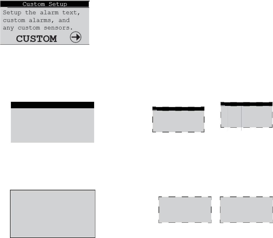
43
E2
Series Controller Operation Manual
programmed to manage the dual power auto transfer
sequence. The ability to select primary power sources
and manually switch them is available with this screen.
5.5.7.7
Custom Alarm Setup
The identifiers A and B may be replaced with Pre and Alt as an
option when the controller is configured at the factory. In such
case, power source A is termed Pre (Preferred); power source B is
termed Alt (Alternate).
From the Service>Options>Custom Setup screen, press the Enter key to access
a menu to set-up the custom alarms and sensors. Any controller alarm or signal
failure will activate the summary alarm output. Upon receiving an alarm indication,
the user may press the alarm key and call up alarm screen messages. The E²
controller may also monitor a customer supplied alarm input device. One set of
Customer Alarm input terminals is standard and up to two more may be added as
an option.
5.5.7.7.1
Customer Alarms
A Customer Alarm input may be used to activate the Summary Alarm relay and show a Customer Alarm message in the alarm
display screen. A Customer Alarm message may simply be displayed as CUSTOMER ALARM # as shown below, press and use
the and arrow keys to construct a specific alpha/numeric message in the line stating the specific alarm condition in their own
terms; for example, GAS DETECTION, INTRUSION ALARM, etc. The Customer Alarm message may be set-up on one line
with up to 20 characters.
E² controllers may be equipped with up to 2 additional Customer Alarms as an option.
5.5.7.7.2
Custom Alarms
In addition to the Summary Alarm, the E² controller may activate a Custom Alarm output and energize a designated n.o./n.c. relay.
A custom alarm output is set up by adding the binary bitmask numbers assigned to the specific alarms and signal failures that need
to be monitored and then entering them in the Custom Alarm Setup screen shown below:
E² controllers may be equipped with up
to 2 additional Custom Alarms as an
option.
The operator can select any mix of the 80 alarm variables as shown in the tables that follow. As an example, for a custom alarm
based only on the occurrence of water detection, condensate pan, pump, failure of the return temperature and humidity sensors
the operator would enter the following bitmask values for the applicable alarm numbers and enter 0 for the rest:
Custom Alarm number 1 - 8: Water detection (No. 7) = 64
Custom Alarm number 9 - 16: Condensate pan (No. 9) + Pump (No. 14) = 33 (1+32)
Custom Alarm number 41- 48: Return temperature (No. 41) + Return humidity (No. 42) = 3 (1+2)
The custom alarms are set up by entering the bitmask totals developed from the following tables.
CUSTOMER ALARM 1
Customer Alarm2 Text
CUSTOMER ALARM 2
Customer Alarm3 Text
CUSTOMER ALARM 3
Custom Alarm 2 Setup
1-8: 000 9-16: 000
17-24: 000 25-32: 000
33-40: 000 41-48: 000
49-56: 000 57-64: 000
65-72: 000 73-80: 000
Custom Alarm 3 Setup
1-8: 000 9-16: 000
17-24: 000 25-32: 000
33-40: 000 41-48: 000
49-56: 000 57-64: 000
65-72: 000 73-80: 000
Customer Alarm1 Text
Custom Alarm 1 Setup
1-8:
235
9-16:
63
17-24:
252
25-32:
0
33-40:
3
41-48:
255
49-56:
63
57-64:
255
65-72:
15
73-80:
0
44
E2 Series Controller Operation Manual
Alarms 1 to 8
No. Description
Bit
mask
Default
1
Emergency shutdown
1
1
2
Remote shutdown
2
2
3
Customer alarm 1
4
0
4
Airflow
8
8
5
Filter
16
0
6
Fire/smoke
32
32
7
Water detection
64
64
8
Heater over temperature
128
128
Factory Default Bitmask Total 235
Alarms 9 to 16
No. Description
Bit
mask
Default
9
Condensate pan
1
1
10
Circuit 1 low pressure
2
2
11
Circuit 1 high pressure
4
4
12
Circuit 1 low pressure
8
8
13
Circuit 1 high pressure
16
16
14
Pump
32
32
15
Dual power input A
64
0
16
Dual power input B
128
0
Factory Default Bitmask Total 63
The default values (shown in bold italics) are factory set to generate a custom alarm output on any of the major alarms and
any sensor failure. Only the enabled sensors can generate an alarm. To enable an additional custom alarm, add the alarm
bitmask number to the factory default total and enter the new total for the applicable alarm numbers in the Custom Alarm Setup
screen. If an alarm condition appearing in the following tables is detected, it needs to be reset at the unit's display terminal or
via the BMS.
Alarms 17 to 24
No. Description
Bit
mask
Default
17 Customer alarm 2 1 0
18
Customer alarm 3
2
0
19
Humidifier
4
4
20
Flow alarm CW1
8
8
21
Flow alarm CW2
16
16
22
Fan alarm 1
32
32
23
Fan alarm 2
64
64
24
Fan alarm 3
128
128
Factory Default Bitmask Total 252
Alarms 25 to 32
No. Description
Bit
mask
Default
25
High temperature
1
0
26 Low temperature 2 0
27 High humidity 4 0
28 Low humidity 8 0
29 High water temperature CW1 16 0
30
Low water temperature CW1
32
0
31
High water temperature CW2
64
0
32 Low water temperature CW2 128 0
Factory Default Bitmask Total 0
45
E2
Series Controller Operation Manual
Alarms 33 to 40
No. Description
Bit
mask
Default
33
Loss of power
1
1
34 Fan alarm 4 2 2
35 Damper Feedback 4 0
36
Pre Filter
8
0
37 Pre HP C1 16 0
38 Pre HP C2 32 0
39 Reserved 64 0
40
Reserved
128
0
Factory Default Bitmask Total 3
Alarms 41 to 48- (Sensor Failure Alarms)
No. Description
Bit
mask
Default
41
Return temperature
1
1
42
Return humidity
2
2
43
Remote temperature
4
4
44 Remote humidity 8 8
45
EWT1 temperature
16
16
46 LWT1 temperature 32 32
47
EWT2 temperature
64
64
48
LWT2 temperature
128
128
Factory Default Bitmask Total 255
Alarms 49 to 56- (Sensor Failure Alarms)
No. Description
Bit
mask
Default
49
Circuit 1 discharge pressure
1
1
50
Circuit 1 discharge pressure
2
2
51
Economizer return temperature
4
4
52
Economizer return humidity
8
8
53 Economizer outdoor
temperature
16 16
54
Economizer outdoor humidity
32
32
55
Reserved
64
64
56 Reserved 128 128
Factory Default Bitmask Total 255
Alarms 57 to 64- (Sensor Failure Alarms)
No. Description
Bit
mask
Default
57
Static air pressure
1
1
58 Differential air pressure 2 2
59
Dewpoint
4
4
60
Airspeed
8
8
61
Circuit 1 suction pressure
16
16
62
Circuit 1 suction pressure
32
32
63
Circuit 1 suction temperature
64
64
64
Circuit 2 suction temperature
128
128
Factory Default Bitmask Total 255
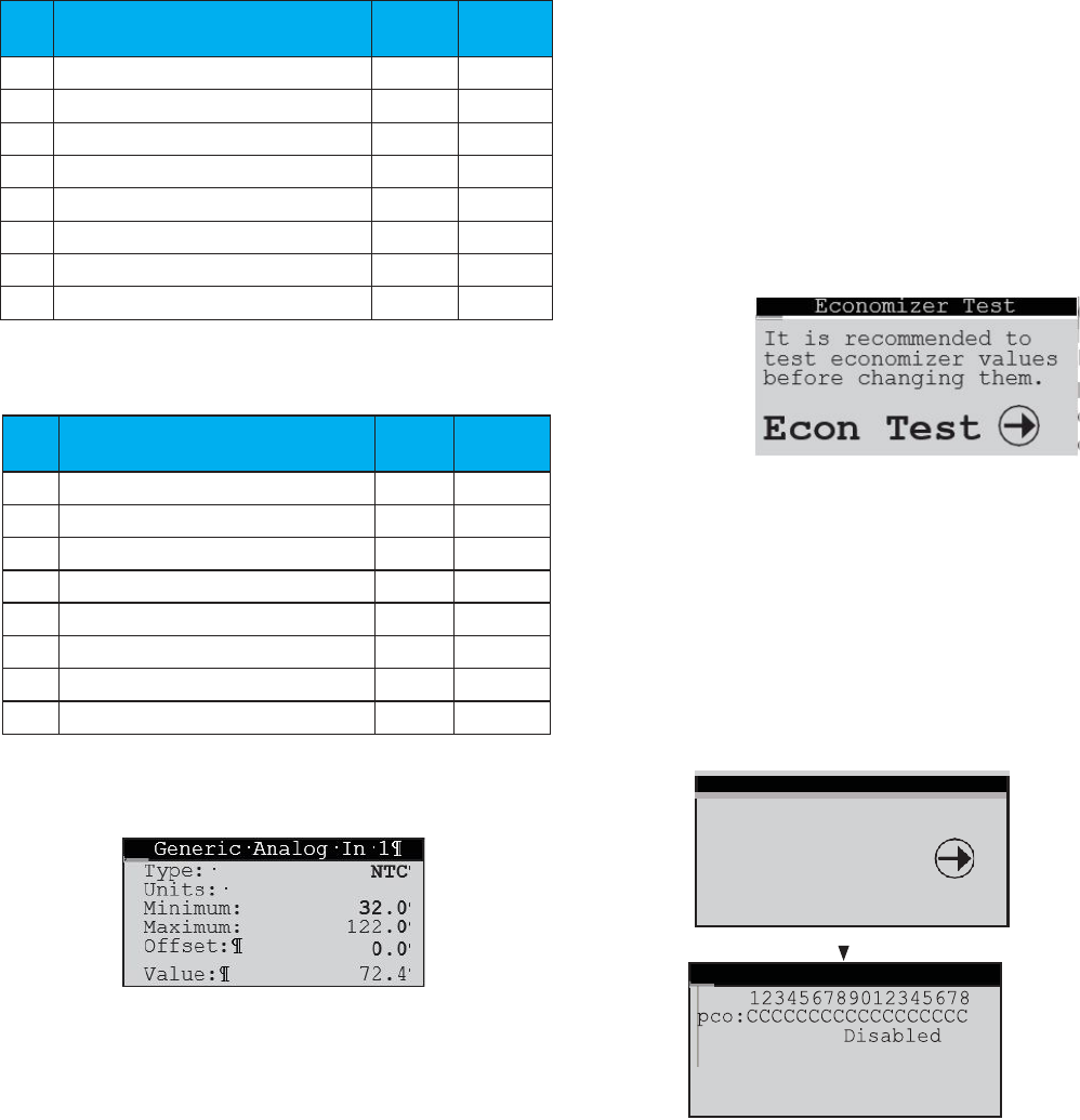
46
E2 Series Controller Operation Manual
Alarms 65 to 72
No. Description
Bit
mask
Default
65
Custom Sensor 1
1
1
66
Custom Sensor 2
2
2
67
Custom Sensor 3
4
4
68 Custom Sensor 4 8 8
69 Reserved 16 0
70 Reserved 32 0
71 Reserved 64 0
72
Reserved
128
0
Factory Default Bitmask Total 15
Alarms 73 to 80
No.
Description
Bit
mask
Default
73 System off 1 0
74 BMS Keep alive off 2 0
75 Reserved 4 0
76
Reserved
8
0
77
Reserved
16
0
78 Reserved 32 0
79 Reserved 64 0
80 Reserved 128 0
Factory Default Bitmask Total 0
5.5.7.7.3
Custom Sensors Screens
If the controller is configured to monitor custom sensors
(optional), a display screen is provided to set-up the
parameters foreach custom sensor the controller is configured
to use (up to 4). Each screen allows the selection of parameters
specifically for the sensor to which it's assigned.
Type = NTC, 4-20mA, 0-1volt or 0-5volt.
Units = °F, °C, %, psi, miwg, fpm, mbar, m/s or none (default).
From these screens’ sensors are also assigned a Minimum and
Maximum range for the unit of measure selected. For example, if
a 0-50 °C sensor is being used, enter 0 for Minimum and 50
for Maximum. To display the units of measure as °F instead of
°C in the Information menu screens, convert the minimum and
maximum values (0-50 °C = 32-122 °F) and enter the values to
be displayed in °F(32 for Minimum and 122 for Maximum). Sensor
values outside of the minimum and maximum values will generate
a sensor failure alarm.
The current value being read by the sensor appears at the
bottom of the screen.
5.5.7.8 Economizer Test
The Service>Options>Economizer Test screen appears only if
the controller is equipped for Economizer operation.
If the Enter key is pressed, it allows the operator to enter a
sub-menu to perform a functionality test of the economizer
mode and experiment with different settings of temperature
and dewpoint. Pressing the Down arrow key advances the
display to the Options>Economizer Option screen which
allows the Economizer mode to be enabled. See Section 6.0
for a detailed description of Economizer operation and see
Section 6.3 for information on setting the operating
parameters available in these screens.
5.5.8 Digital In
SERVICE
Options
Digital In
Run Hours
The Service>Digital In screen is provided for information only.
It shows the state of each digital input as either Closed (+24 V)
or Open (Gnd). Ex1 to Ex5 are the expansion I/O modules. To
the right is Disabled or Enabled to show which expansion I/O
modules are active.
Ex1:CCCC
Ex2:CCCC
Enabled
Ex3:
Disabled
Ex4:
Disabled
Ex5: Disabled
Digital Inputs
47
E2
Series Controller Operation Manual
BMS Communications
5.5.9 Run Hours
SERVICE
Digital In
RUN HOURS
BMS Comm
From the Service>Run Hours menu, use of the Up and Down (
arrow keys to access a menu of the component run hours
display screens that are applicable to the A/C unit. Each
screen displays the number of run hours and number of starts
logged for the component (i.e. blower, pump, compressor,
heater, humidifier, etc.). The run hours and starts values may be
reset to 0. The values displayed in each screen are the values
logged since the last time the screen was reset.
5.5.10 BMS Communication
The Service>BMS Comm menu is used to set-up parameters to
allow a BMS (BAS) to interface with the controller. See Section
7.3 for a description of this screen and instructions for setting
up BMS communication.
5.5.11 Work Group Screens
The Service>Group display screens, shown below, appear but
are only functional if the controller is configured to manage two
or more units together as a group. They allow configuration of
the parameters that apply to how the A/C units interact in the
work group.
SERVICE
BMS Comm
GROUP
Save Cfg
Assist>Group
Shadow>Group Menu
Group Rotation
Force Rotation No
Number of Weeks 0
Number of Days 0
Rotate every 0 Hrs
Cur lead 1
Next lead 0
Capacity Assist
Assist Time 300s
Cooling Cut in 1.0°F
Cut out 0.0°F
Heating Cut in -1.0°F
Cut out 0.0°F
See Section 7.2.6 for additional Service>Group screens and
for a detailed description of how work groups are set up and
information on setting the operating parameters available in
these screens.
5.5.12 Save Configuration
The default setpoints may be restored and passwords may be
changed from the Service>Save Cfg menu.
Group
Con
fi
guration
Unit ACTIVE
Total in Network 0
Number of Active 0
Lead Unit 0
Group
Con
fi
guration
Unit ACTIVE
Shadowing Unit 1
2nd Shadow Unit 9
0018hrs
1
Off
Blower
Starts
Reset
Starts/Run Hours
Address: 01
Baud Rate: 19200
Protocol: BACnet
BMS Keep Alive: 000
2nd Shadow Unit 10
Shdw Smoke Shutdown: Yes
17
17
Shared Display1
Shared
Display2
1st Shadow Unit
Share/Shadow Setup
48
E2 Series Controller Operation Manual
The first Service>Save Cfg menu screen allows the operator
to save any adjustments made in Service level menu screens
as the new "Customer" parameters or, restore the controller to
the previously saved "Customer" parameters. The user may
also restore the controller to original factory default parameter
values shown in Table 2.
Use the Enter key to move the flashing cursor to the
applicable field and confirm by pressing the Up or Down
arrow key. The word No will momentarily change to Yes,
indicating the command has been accepted. Then press the
Enter key sequentially until the flashing cursor returns to the
top left corner of the screen.
The table that follows are some of the Factory default
parameters.
Table 5. Factory Default Setpoints
The second Service>Save Cfg menu screen allows new
passwords to be set for entering the Control and Service
menus.
5.5.13 Factory Menu
The Factory menu may be accessed from the Service>Factory
screen. The factory level password must be entered to gain
access to the menu. Contact STULZ Product Support for the
password and for guidance when adjustments must be made
at this level.
PARAMETER DEFAULT VALUE
Temperature Setpoint
72 °F
Cool Stage 1 Cut-in 74 °F
Cool Stage 1 Cut-out 72.3 °F
Cool Stage 2 Cut-in 75 °F
Cool Stage 2 Cut-out 73 °F
Heat Stage 1 Cut-in 70 °F
Heat Stage 1 Cut-out
71.7 °F
Heat Stage 2 Cut-in 69 °F
Heat Stage 2 Cut-out 71 °F
Heat Stage 3 Cut-in 68 °F
Heat Stage 3 Cut-out 70 °F
Humidity Setpoint 45% RH
Humidify Cut-in
40% RH
Humidify Cut-out
43% RH
Dehumidify Cut-in 50% RH
Dehumidify Cut-out 47% RH
Control:
Service:
Set Passwords
49
E2
Series Controller Operation Manual
6.0 ECONOMIZER OPERATION
An economizer mode is available for applications using
outdoor air-side economizing. The E² controller manages the
economizer mode to use outside air and minimize the need for
conventional cooling. It also monitors the outside air dewpoint
so as to not introduce air that is either too wet or dry for the
desired conditions.
To enable economizer operation, an outside air
temperature/humidity sensor and a return air temperature/
humidity sensor are provided to control the economizer
damper system (see Figure 9).
The economizer mode is to be used with an opposing pair
damper set-up, i.e. when the external outside air intake
damper is set at 30% open, the room return damper moves
to 70% open.
The controller only provides a single output signal intended to
control the outside air damper. It is up to the designer of the
damper system to use that signal to control a reverse-acting
room return air damper. If the room return air damper is not
interlocked to run in reverse or if it is missing altogether, true
100% outside air cannot be achieved.
NOTE: The mixed air sensor is the return air sensor inside the
A/C unit.
A proportional control signal (1-10 VDC) allows the external
outdoor air intake damper and room return air damper to
modulate their positions between 0-100% open to maintain
user supply air setpoints. The controller seeks to achieve the
most energy efficient mixture of outside air and return air to
satisfy the temperature/humidity demand and maintain the
setpoints.
Damper control settings are determined by examining both the
temperature and dewpoint properties of the outdoor air and
the return air. The outdoor air damper output signal will lockout
if the outdoor air temperature or dewpoint lie outside of the
user adjustable setpoint values. A return air (mixed air) sensor
is included to limit economizer function if low limit alarms are
reached.
The economizer damper signal can be adjusted to a minimum
output value to allow only the least amount of outside air to
enter for meeting air quality ventilation requirements.
Figure 9. Economizer Operation
Temperature/Humidity
Temperature/Humidit
Temperature/Humidit
y
50
E2 Series Controller Operation Manual
6.1 Economizer Information Menu Screens
The following display screens are available in the Information menu (Section 5.2) only if the unit is equipped for economizer
operation by the factory. The screens display key operating parameters for the economizer mode.
6.1.1 Economizer Return Air Sensor
If the controller is configured for economizer operation, a display screen indicates
the temperature and relative humidity as measured by the return air temperature
and RH sensor inputs. The return dewpoint is calculated by the controller based on
the return air temperature/humidity sensor inputs.
6.1.2 Economizer Outside Air Sensor
This screen indicates the temperature and relative humidity as measured by the
outside air temperature/humidity sensor. The display also indicates the degree to
which the outside air damper is opened as a percentage. The outside air dewpoint
is calculated by the controller based on the Outside Air temperature/humidity
sensor inputs.
6.2 Economizer Service Menu Screens
The screens that follow allows economizer operation to be set
up and tested and setup. They are available in the Service menu
only if the economizer option is enabled by the factory.
6.2.1 Economizer Test
From the Service>Economizer Test screen, press the Enter
key to enter a sub-menu to perform a functionality test of the
economizer mode and experiment with different settings of
temperature and dewpoint. Press the Down arrow key to
advance the display to the Service>Economizer Options
screen where the economizer mode is actually enabled (see
Section 6.3.1).
It is recommended to use the regular dewpoint settings first to
familiarize oneself with the economizer operation. Using the
factory default settings, the dehumidification dewpoint is 52.3
degrees, the humidification dewpoint is 46.4 degrees, and the
dewpoint through the setpoints is 49.5 degrees. Figure 10
depicts the default economizer zone as bounded by the
rectangle A B C D.
Figure 10. Default Economizer Zone
The factory default offsets may be adjusted to expand the
operating zone as represented by A
1
B
1
C
1
D
1
. The TEST Limits
screen is used to adjust the high and low temperature and if
enabled, modify the four dewpoint offsets. The starting
dewpoint offset values shown are drawn from the default ones
of +2.8 (49.5 + 2.8 = 52.3) and two arbitrary ones (-3.3 and -
5). The offset values do not need to match nor does the
resultant shape have to be a rectangle.
TEST Limits
Econ
High
Temp:
80°F
Econ
High
+DP:
2.8
Econ
High
-DP:
-5.0
Econ
Low
Temp:
30°F
Econ
Low
+DP:
2.8
Econ
Low
-DP:
-3.3
This section does
not actually control
the economizer. It is
for test purposes
only.
Expand dewpoint? Yes
TEST Economizer
Econ Return Sensor
00.0°F
00%rh
econ return DP 00.0°F
Econ Return Sensor
00.0°F
00%rh
econ return DP 00.0°F
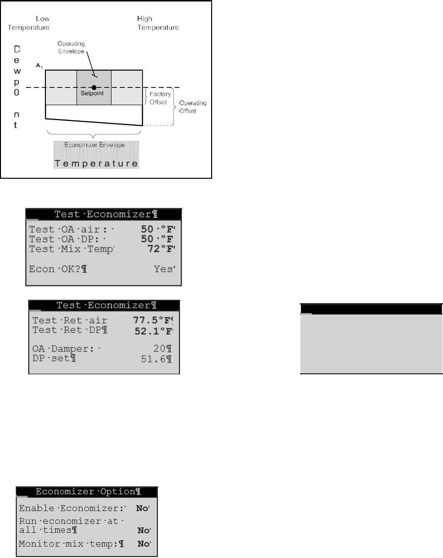
51
E2
Series Controller Operation Manual
Figure 8 depicts the expanded dewpoint where the lower
dewpoint offsets of C and D have been replaced by C and
The controller monitors the outdoor air and ceiling return air
conditions and adjusts the damper setting to get the mixed air
D
1
.
1
Figure 11 . Example Economizer Zone
The temperature setpoint and dewpoint may be
changed in the Control menu if desired. The controller
displays the damper setting for the input conditions
(20%) and the resulting dewpoint (51.6). The operator
can vary the damper setting to see how it effects the
overall mixed air temperature and dewpoint coming into
the A/C unit.
conditions as close as possible to the desired temperature
setpoint. If the outdoor air conditions are outside of the user
adjustable setpoints, the damper remains closed at 0%.
In the simple case where both the outdoor air and ceiling
return air temperatures are above the temperature setpoint
and outdoor conditions are within the economizer operating
envelope, the colder of the two temperatures is selected which
then drives the damper to 0% (full ceiling return air) or 100%
(full outdoor air). Temperatures on either side of the setpoint
cause the damper to open to a "New Damper" position such as
20% as shown in the above screen.
The damper position is determined by the air temperatures,
but the resultant mixed air dewpoint is also taken into account.
In this example, the ceiling return (room conditions) started at
52.1 degrees dewpoint and the outdoor air is at 50 degrees
dewpoint. The incoming mix is at 51.6 degrees dewpoint. If the
A/C unit or the overall conditioned space has no mechanism
for humidification, the ceiling return dewpoint will drop which
then causes the mixed dewpoint to drop even lower.
Eventually, the room dewpoint will match the dewpoint of the
outside air. The speed at which the dewpoint drops depends
on the airflow rate and the size of the room.
6.3 Enabling Economizer Operation
6.3.1 Economizer Option Screen
From the Service>Economizer Option screen the economizer
mode is enabled by entering Yes in the field of the first line. If
Yes is entered in the second line it allows economizer damper
control to continue operating even when the A/C unit is turned
off. In the third line the economizer mixed air monitoring function
may be selected by the user.
With the Monitor mix temp economizer selection set
to Yes, the controller modulates the damper according to
the external sensors and adjusts it accordingly if the mixed
air sensor is not at the setpoint. This is intended for use in
closed duct systems and allows for any inaccuracies in the
damper system to be accounted for.
If Monitor mix temp is set to No, the controller will
simply move the damper based on the external sensors and
the desired setpoint. This is used for an open duct system
where the external air comes into the room, but not solely
through the A/C unit.
Adjust Mix Temp: 72°F
New Damper 20
New Mix DP
51.6°F
Adjust Damper: 000
New Mix Temp 77.5°F
New Mix DP 52.1°F
Test Mix <-> Damper
-5.0
D
1
C
1
-
3.3
2.8
B
1
2.8

52
E2 Series Controller Operation Manual
6.3.2 Economizer Screen Two
6.3.3 Economizer Screen Three
The third Service>Options>Economizer screen allows the
operator to change the economizer high temperature value
and expand the dewpoint boundaries. The Econ Low +DP
and Econ Low –DP are offsets from the dewpoint value that
passes through the temperature and humidity setpoint.
Economizer
Expand dewpoint? Yes
Econ High Temp: 80.0°F
Dehumidify DP: 52.3
Econ High +DP: 3.0
Econ High -DP: -3.0
Econ Low +DP: 3.0
Econ Low -DP: -3.0
Econ Low Temp: 30.0°F
Humidify DP: 46.4
Economizer
53
E2
Series Controller Operation Manual
7.0 COMMUNICATION WITH
THE CONTROLLER
It is possible for the STULZ E2 controller to communicate in
multiple ways. The controller may be set up to use a pLAN
network to link with additional E² controllers to create a work
group consisting of multiple A/C units (see Figure 12 and
Section 7.1).
Using a BMS interface port, the controller may also be
connected to a BMS for monitoring and control of data points
using a multitude of different serial communication protocols
(see Section 7.3).
The second Service>Options>Economizer screen allows the
operator to change the economizer high temperature value
and expand the dewpoint boundaries. The Econ High +DP
and Econ High –DP are offsets from the dewpoint value that
passes through the temperature and humidity setpoint.
7.1 Work Groups
The controller may be networked with a group of A/C unit
controllers via an RS485 connection to manage their outputs
as a system in an N+M (M = number of standby units) group.
The controllers from up to seven additional A/C units may be
tied to a Lead controller. The number of units to be assigned as
Active, Capacity Assist or Standby duty is to configured by the
factory however, they may configured in the field (see Section
7.2.6) with assistance from STULZ Product Support. A unit
may also be designated as "Out of Service" (see Section 7.1.4).
Figure 12. Configuring Multiple A/C Units
54
E2 Series Controller Operation Manual
The Main screen of each unit in the work group indicates that
unit's duty assignment in the bottom field. If the controller is the
group Lead, it is indicated in the bottom field also.
Multiple Unit Display Screen
One controller may be designated as the work group lead and
networked with the controllers from a series of up to 7
additional A/C units. If configured for multi-unit operation, the
work group lead controller display panel allows access to the
same data and group control sensor choices that are available
from networked system controller display panels.
The controller for each A/C unit in a group may be manually
called up from the Main display of the Lead unit via the PLAN
network. From the Main display, simultaneously press the Up
and Down arrow keys. This allows the Main display to access
the controller in the adjacent A/C units in the group. From the
Main screen, press the Up arrow key to view the Software
Version/Date display screen to verify the accessed shadow
unit's PLAN address appearing in the upper left corner of the
screen.
From there, scroll through the menu screens as described in
Section 3.4. Each time the Up and Down arrow keys are
simultaneously pressed it sequences the display to the next
grouped unit's controller. Again, access this screen to verify the
PLAN address of the unit that has been interfaced with.
7.1.1 Capacity Assist
The Capacity Assist option can be used to maximize efficiency
for conservation of energy and to more precisely control
capacity at low demand. This feature enables Active A/C units
to handle the demand up to a certain temperature/humidity
setpoint and then enables additional units to begin operating
gas needed. If the Active A/C units are running and unable to
satisfy the demand, Capacity Assist A/C unit(s) may be
programmed to turn on to assist the Active units.
Each Capacity Assist unit may set to control operation based
on its local temperature/humidity sensor values or control
operation based on network sensor values transmitted from
the Lead controller. Multiple capacity assist units are typically
set with each unit in the group assigned incrementally
increasing/ decreasing offsets for cooling, heating,
humidifying and dehumidifying so they will turn on one at a
time only if the unit(s) currently operating are unable to satisfy
the demand. They should incrementally turn off as each unit
reaches its cut-out setpoint, while active A/C unit(s) continue
to maintain room conditions at the desired level.
7.1.2 Standby
If the lead controller in the work group loses a signal
acknowledgement from an active A/C unit in the group,
that A/C unit is deemed as failed or taken out of service.
The failed unit will be replaced with the first available
standby unit from the work group. The standby unit is
cycled on and designated as the new active unit in place of
the failed unit.
7.1.3 Unit Rotation
In this mode, the Lead controller will rotate duty between
the grouped A/C units to promote equal run time and will
rotate the role of group lead. When set-up for unit rotation,
the A/C units will rotate duty in order of their group
addresses. Active, Capacity Assist and Standby units are
all in the rotation cycle so even a standby unit will be cycled
into active duty on a scheduled basis. The rotation time
period is typically 1-week; however it may be set by the
user via the Factory menu. Call STULZ Product Support
for assistance when accessing the Factory menu.
7.1.4 No Rotation
A/C units in the group may have their duty assignments
locked so they do not join the rotation cycle (capacity assist
and standby no-rotation units cannot take the lead). In this
case the message No_Rot appears after the duty
assignment displayed in the main screen.
An Active_No_Rot unit is always On. It will never be
capacity assist or standby. An Active_No_Rot unit may
take the role as lead controller when the rotation puts it as
the first active unit. Units designated as "Out of Service" do
not rotate nor can the controller take the role of lead.
7.1.5 Out of Service
A unit may be removed from the group entirely by placing it
Out of Service. In this mode, the unit will not operate. A unit
may be placed in this mode as a safety measure to prevent
it from unexpectedly starting when performing
maintenance or repairs.
00%rh
dp 00.0°F
Lead
01/01/09 00:00:00
00.0°F
Unit On
ACTIVE
ACTIVE_No_Rot
00%rh
dp 00.0°F
01/01/09 00:00:00
00.0°F
Unit On

55
E2
Series Controller Operation Manual
7.2 Setting Up a Work Group
A workgroup can consist of up to eight controllers (I/O boards) with pLAN addresses 1 to 8. Their corresponding display terminals
will be assigned pLAN addresses from 32 down to 25. The E² controller program is defaulted with the controller address set to 1
and its terminal (display) address set to 32. As such, a normal stand-alone controller does not need any changes made to either the
controller or the terminal address. The method to setting up work groups is to retain the first (group lead) controller's pLAN address
as #1 and terminal address as #32 so that the sum of the addresses equals 33. The first controller added to the group is assigned
pLAN address #2 and its terminal is assigned address #31, the sum of which again equals 33.The sum of the controller and
terminal address numbers must always equal 33.
The A/C units in a work group should ALWAYS start with controller address 1 and go up from there. DO NOT skip over controller
addresses. The list of suitable controller/display terminal address pairs is shown below:
Corresponding A/C Unit Controller to Terminal pLAN Addresses
Controller (I/O board)
1
2
3
4
5
6
7
8
Display Terminal 32 31 30 29 28 27 26 25
Assign the terminal and controller I/O board addresses for each controller to be grouped. Review Sections 7.2.1 to 7.2.3 first,
before turning power on and the assigning addresses. Do not interconnect the controllers together before assigning their terminal
and I/O board pLAN addresses.
The first step is to change the terminal address of each controller to 0 referring to Section 7.2.1. Set the terminal address to 0
before assigning the controller (I/O board) address.
Note: If the terminal remains inactive (no key is pressed) for more than 30 seconds, the group set-up procedure is exited
automatically, without saving any changes. Configure the Terminal Address.
7.2.1 Configure the Terminal Address
The address of the terminal (display) can only be configured if its RJ11 telephone jack is connected to the I/O control module in
the electric box and power is turned on. The factory default value for the display terminal address is 32. To reassign the terminal
address, press and hold the Up, Down and Enter keys simultaneously for five seconds until the Address Configuration screen
shown below appears with the flashing cursor in the top left corner:
1.
To change the address of the terminal (Display address setting), press the Enter key
once. The cursor will move to the address field (nn).
2.
Using the Up, Down keys, select 0 and confirm by pressing Enter .
The Display Address Changed screen will appear indicating the display address selected
is not the same as the one saved and the new value will be saved to memory.
3.
Once the terminal address is set to zero, cycle the power to the unit Off and then back On.
If the Display address setting field is set to 0, the terminal will communicate with the
controller using point-to-point protocol (not pLAN). The display field I/O Board address
will disappear as it has no meaning until the controller I/O board pLAN address is set.
7.2.2 Configure the I/O Board pLAN Address
Immediately after turning power back on, press and hold the Alarm and the Up ) Arrow keys
Address Configuration
Display Address Changed
Simultaneously for 10 to 15 seconds. First a display message self-test. Please wait will appear then the pLAN Address Configuration
screen shown below will appear. Don’t press the ) key, the cursor is already in the modifiable field.
Press the key to set the pLAN address (#1 – 8) for the controller (I/O Board). The pLAN
address #1 is already assigned by default to the first (Lead) controller in the group. Address
2 is to be assigned to the first controller added to the group (address #3 is to be assigned to
the second controller added and so on). Then press the key to confirm the selection. A
message NO LINK will appear.
Controller Address Configuration
Display address
changed
PLAN ADDRESS: 1
UP: INCREASE
DOWN: DECREASE
ENTER: SAVE & EXIT
D
isplay address
setting..........: nn
I/O Board address: xx

56
E2 Series Controller Operation Manual
Next, press the Up , Down and Enter keys simultaneously. Reconfigure the terminal address following the steps in Section again.
This time set the terminal address to match the corresponding controller I/O board address. If the controller is assigned address 2,
then the corresponding terminal address should be set to 31 as shown in the table on the preceding page. If the next controller
is assigned address 3, the corresponding terminal should be set to 30.
After setting the correct terminal address, press the key once to confirm the selection. A message NO LINK will appear. At this
point, the terminal has been set with the correct address for the controller and the controller has been set for the terminal, but now
they need to be assigned to each other.
7.2.3 Assign the Terminal to the Controller
1.
Access the Terminal Address Configuration screen again using the Up , Down and Enter keys.
2.
Press the key until the cursor moves to the field I/O board address.
3.
Using the keys, enter the address (1 – 8) for the controller I/O board.
4.
Press the key twice to display the Terminal Configuration screen.
5.
Here too, the key moves the cursor from one field to the next, and the Up and Down keys
change the value of the current field. The field P:0_ depicts the pLAN address (1 – 8)
assigned to
the I/O board. In the example shown, the controller has been assigned address 2.
6.
Press the key to move to the field Trm1 xx. The field represents the address of the
Terminal Configuration
P:02 Adr Priv/Shared
Trm1 31 Pr
Trm2 None --
Trm3 None -- Ok?No
57
E2
Series Controller Operation Manual
terminal associated with the controller. Using the keys enter the address (25 – 32) of the terminal assigned to the
controller (I/O board). In the example shown, address 31 has been entered for the first A/C unit added to the
group.
7.
The Priv/Shared column indicates the type of terminal. The workgroup is setup using private terminals.
8.
Do not change the value (Pr). Press the key to move to the last field
9.
Select the field Ok? No, choose Yes using the Up and Down keys and confirm by pressing to save
the data and exit the group set-up procedure.
10.
Referring to the wiring diagram provided with the A/C units, interconnect the units together with the pLAN
cable(s) provided.
7.2.4 Fault messages
If the terminal detects the status of the I/O board it is associated with is off-line, the display shows the message:
I/O Board xx fault. If this appears, check the Signal LEDs on the controller (see Figure 3) for an error signal.
See Section 8.4 for guidelines on analyzing the signal LED’s.
On the other hand, if the terminal receives no signal from the network, the display shows the following message:
NO LINK. If this appears, check the pLAN cables and ensure they are connected properly. Also, check the addressing
(refer to Section 7.2).
7.2.5 Displaying the Network Status and Firmware Version
Once each A/C unit is configured with its new controller and terminal pLAN address, the entire network set up may be examined.
Press the group set up keys together as done to access the Address Configuration screen but continue holding after the Address
Configuration screen appears for at least 5 seconds until the Network Status (NetSTAT) screen appears.
The Network Status screen, shown below, provides overview of the pLAN group indicating which and how many devices are
connected and the corresponding pLAN addresses.
: Controllers (I/O Boards) active in network
: Terminals active in
network
: No device
connected
The example shown represents:
Network Status
NetSTAT Term:32
1 8
9 16
17 24
25 32
Press Enter to quit
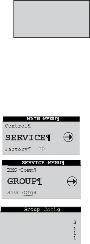
58
E2 Series Controller Operation Manual
Controllers active in network, addresses: 1, 2, 3. ...
Terminals active in network, addresses: 30, 31, 32The terminal for controller 1 is always addressed 32; the terminal for controller
2 is always addressed 31, and so on such that the sum of the controller address number and the terminal address number always
equals 33. Therefore, when viewing controller number 1, its terminal address will be 32. When viewing controller number 2, its
terminal address will be 31, and so on.
Press a or arrow key to display the next screen showing the version of the firmware residing in the terminal.
Firmware Version
To exit the Network Status menu, press Enter.
The next step is to access the Service>Group screens used to configure the work group parameters (Section 7.2.6).
7.2.6 Configure Work Groups
Enter the Service>Group menu screens when multiple A/C units are grouped. These menu screens allow grouping parameters
(duty, rotation, offsets, etc.) to be defined for the A/C units in the work group. These screens should be accessed after setting up
the work groups (Section 7.2). The Service>Group menu screens may be accessed from the main screen by pressing the Prg key
and scrolling through the menu selections until the word SERVICE appears in the center of the screen.
Press the Enter
( )
key twice and a screen will appear to enter the password for the Service level.
Once the Service level password is accepted, press Enter to call up the menu screens. From here,
press the Up
( )
) or Down arrow keys to scroll through the Service menu selections.
When the word GROUP appears in the center of the screen, press the Enter key to access the
Service>Group menu screens. From here, use the Up ( ) or Down ( ) arrow keys to scroll through
the Service>Group menu selections.
Service>Group>Group Config (Screen 1) See table below.
NOTE: Standby units are added to the number appearing in the Total in Network field although
no field id provided in this screen indicating the number of stand by units that are part of the
group. To determine the number of standby units, subtract Min Number Active + Min Number
Assist from Total in Network. In the example shown there is one standby unit.
pGD1 V1.7
Feb 28 2006
HW:A
Unit ACTIVE
Total in Network
Min Number
Active Min
Number Assist
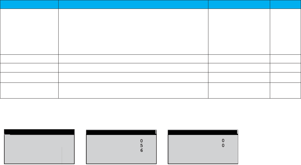
59
E2
Series Controller Operation Manual
Display
Description
Variables
Default
Unit
Assign the duty of the A/C unit within the group.
The duty must be assigned for each A/C unit at its local display
terminal.
Out of Service
Active
Standby
Assist
Active_No_Rot
Standby_No_Rot
Assist_No_Rot
Active
Total in Network
Enter the total number of A/C units in the group.
0 to 8
0
Min Number Active
Enter the total number of active A/C units in the group.
0 to 8
0
Min Number Assist Enter the total number of assist A/C units in the group.
0 to 8
0
Lead Unit
Identifies which A/C unit controller is currently the lead unit in
the group.
1 to 8
0
From the Group Rotation screen, program the controller to rotate operation of the A/C units in the group to promote equal run
times. Three methods are available for the rotation: Multi-week basis, multi day basis and multi hour basis.
1)
On a multi- week basis 2) On a multi-day basis 3) On a multi-hour basis
Service>Group>
Group Rotation
(Screen 2)
Monday
18
No
1
Force Rotation
Number of
Weeks
Day of Week
Hour of the
Day
Cur lead 1
Next lead 0
Group Rotation
Group Rotation
Force Rotation
No
Number of Weeks
Number of Days
Hour of the Day
Cur lead 1
Next lead 0
Group Rotation
Force Rotation
No
Number of Weeks
Number of Days
Rotate every
72
Hrs
Cur lead 1
Next lead 0

60
E2 Series Controller Operation Manual
1)
The multi week basis is selected by setting the number of weeks to a value from 1-99. This will be the number of weeks
between rotations. The next line will show “Day of Week” which may be set to Monday through Sunday. The Hour of the Day is
the hour of the day at which rotation occurs. A setting of 1/Mon/18 will rotate every week on Monday at 6 PM (18:00 hours).
2)
The multi day basis is selected by setting the number of weeks to zero and the number of days to one or more. Now the
number of days becomes an elapsed number of days between rotations. The Hour of Day is the hour of the day at which
rotation occurs. A setting of 0/5/6 will rotate every 5 days at 6:00AM.
3)
The multi hour basis is selected by setting the number of weeks to zero and the number of days to zero. The rotation will
occur after the number of hours has elapsed. A setting of 0/0/72 would rotate every 72 hours
4)
The first two are based on the internal calendar and will survive power losses of the lead unit. If the lead unit is
powered off, the other units will assume temporary roles until the lead unit is powered back up. Upon the lead unit
powering back up, the correct role of each unit is recalculated based on the current calendar date. The hourly
basis is not based on the internal calendar and restarts at zero hours elapsed if the lead unit is powered off and
then back on.
Service>Group>Capacity Assist (Screen 3)
Each A/C unit in the group may be assigned local cut-in and cut-out setpoints for its capacity assist operation. The values
entered are offsets which are applied to the control setpoints established at the lead controller. Each unit in the group
should be assigned incrementally increasing/decreasing offsets for cooling, heating, humidifying and dehumidifying so
they will turn on one at a time only if the unit(s) currently operating are unable to satisfy the demand.
Display
Description
Variables
Default
Assist Time
Enter the delay period for capacity assist unit(s) to
begin operating if it is in the capacity assist mode.
0 to 999 300
Cooling Cut-In
Enter a temperature setpoint offset for cooling
capacity assist operation to begin.
-99.9 to 99.9 1.0
Cut-out
Enter a temperature setpoint offset for cooling
capacity assist operation to stop.
-99.9 to 99.9 0.0
Heating Cut-In
Enter a temperature setpoint offset for heating
capacity assist operation to begin.
-99.9 to 99.9 -1.0
Cut-out
Enter a temperature setpoint offset for heating
capacity assist operation to stop.
-99.9 to 99.9 0.0
Service>Group>Capacity Assist (Screen 4)
The second Service>Group>Capacity Assist screen allows the
adjustment of local capacity assist humidification and dehumidification
setpoints.
Capacity Assist
Assist Time 300s
Cooling Cut in 1.0°F
Cut out 0.0°F
Heating Cut in -1.0°F
Cut out 0.0°F
Capacity Assist
Humid
Cut
in
-4.0%
Cut
out
0.0%
Dehum
Cut
in
4.0%
Cut
out
0.0%

61
E2
Series Controller Operation Manual
Display
Description
Variables
Default
Humid Cut-in
Enter relative humidity setpoint offset for humidifying
capacity assist operation to begin
-99.9 to 99.9 -4.0
Cut-out
Enter relative humidity setpoint offset for humidifying
capacity assist operation to stop
-99.9 to 99.9 0.0
Dehum Cut-in
Enter relative humidity setpoint offset for
dehumidifying capacity assist operation to begin
-99.9 to 99.9 4.0
Cut-out
Enter relative humidity setpoint offset for
dehumidifying capacity assist operation to stop
-99.9 to 99.9 0.0
Service>Group>Group Sensors (Screen 5)
The lead controller polls the controllers from all the A/C units in the work
group and calculates the averaged value of their Temperature sensors,
Humidity sensors and optional Underfloor Pressure sensors. It also
determines the minimum (lowest) temperature sensor value and the lowest
humidity sensor value in the A/C group and conversely, determines the
maximum (highest) temperature sensor value and maximum humidity
sensor value in the A/C group.
Display Description Variables Default
Temp/Hum
Control the work group using the sensors connected
to individual A/C units (Local) or control the work
group using network sensor values transmitted from
the lead controller. To control by network sensors,
select from the network sensor values to be Lead,
Local
Lead
Average
Minimum
Maximum
Local
Average, Min or Max values. The selections made in
Underfloor
this screen will affect all the controllers in the work
group no matter which controller the screen is
accessed from.
Local
Average
Local
Service>Group>Group Averaging (Screen 6)
Each unit in the group may be individually set to allow the lead controller to
include its sensors for determining the group average value when it is
configured for Standby or Capacity Assist operation. If set to no, the lead
controller will not poll that unit’s sensors when calculating the averaged values
Display Description
Variables
Default
Temp/Hum Sensors
Enter Yes for the unit to respond to its local sensors
to enable Standby or Capacity Assist operation. Enter
No
for unit to respond to the Group sensors.
No Yes
Yes
Static Pr Sensors
No Yes
Yes
Service>Group>Group Alarm Setup (Screen 7)
The Group Alarm Setup screen may be accessed on the controller for each
unit to be grouped. Bitmask numbers may be entered to establish which alarm
conditions for that particular unit will initiate a group internal alarm. The group
alarms may be set before the A/C units are wired together.
When a group alarm condition is detected by a unit, it causes that unit to
temporarily switch over from “Active” to “Off” and if another unit is available in
the group, it will rotate into its place. A status massage Off by internal
Use unit sensors when
in Standby or Assist
for Group Averaging
Temp/Hum Sensors Yes
Static Pr Sensors Yes
Group Averaging
Use lead sensor, avg,
min, or max of group
Temp/Hum: Local
Underfloor: Local
Group Sensors
Group Alarm Seup
1-8:
000
9-16:
000
17-24:
000
25-32:
000
33-40:
000
41-48:
000
49-56:
000

62
E2 Series Controller Operation Manual
Alarm will appear in the Main screen of the unit that detected the group alarm and switched off.
See Section 5.5.7.7 for an overview of how to select alarms using bitmask values. The Group Alarms bitmask values are shown in
the following tables. The settings may be viewed at the Info level (see Section 5.2.22). If an alarm condition appearing in the
following tables is detected, it needs to be reset at the unit's display terminal or via the BMS for the unit to return to “Active” and
resume operation.
Group Alarms 1 to 8 Group Alarms 9 to 16
No. Description
Bit
mask
Default
1
Heater over temperature
1
0
2
Humidifier
2
0
3
Pump
4
0
4
Flow alarm CW1
8
0
5
Flow alarm CW2
16
0
6
Customer alarm 1 32
0
7
Customer alarm 2
64
0
8
Customer alarm 3 128
0
No.
Description
Bit
mask
Default
9
Circuit 1 low pressure
1
0
10
Circuit 1 high pressure
2
0
11
Circuit 2 low pressure
4
0
12
Circuit 2 high pressure
8
0
13
CW1 Valve Error 16
0
14
CW2 Valve Error
32
0
15
Damper End Switch
64
0
16
Reserved
128
0
63
E2
Series Controller Operation Manual
Group Alarms 17 to 24
No. Description
Bit
mask
Default
17
Fan alarm 1
1
0
18 Fan alarm 2 2 0
19 Fan alarm 3 4 0
20
Fan alarm 4
8
0
21 Water detection 16 0
22 Condensate pan 32 0
23
Filter
64
0
24 Reserved 128 0
Group Alarms 25 to 32
No.
Description
Bit
mask
Default
25 High temperature 1 0
26
Low temperature
2
0
27 High humidity 4 0
28 Low humidity 8 0
29
High water temperature CW1
16
0
30 Low water temperature CW1 32 0
31 High water temperature CW2 64 0
32
Low water temperature CW2
128
0
Group Alarms 33 to 40
Group Alarms 41 to 48
No.
Description
Bit
mask
Default
41
DX1 discharge pressure
1
0
42
DX2 discharge pressure
2
0
43
Economizer return temperature
4
0
44
Economizer return humidity
8
0
45
Economizer outdoor temperature
16
0
46
Economizer outdoor humidity
32
0
47
Circuit 1 high pressure Pre-alarm
64
0
48 Circuit 2 high pressure Pre-alarm 128 0
Group Alarms 49 to 56
No
.
Description
Bit
mask
De-
fault
49
Static air pressure
1
0
50
Differential air pressure
2
0
51
Dewpoint
4
0
52
Airspeed
8
0
53
Circuit 1 suction pressure
16
0
54
Circuit 1 suction pressure
32
0
55
Circuit 2 suction temperature
64
0
56 Circuit 2 suction temperature 128 0
There are several automatic crossover signals that will cause a
switch over from Unit Active to Unit Off. They are the occurrence of
a remote shutdown command, unit shutdown from a group
alarm, clock schedule or BMS command, fire/smoke detection,
loss of all cooling (all compressors or all CW valves) or loss of
airflow.
No. Description
Bit
mask
Default
33 Return temperature 1 0
34
Return humidity
2
0
35 Remote temperature 4 0
36 Remote humidity 8 0
37 EWT1 temperature 16 0
38
LWT1 temperature
32
0
39
EWT2 temperature
64
0
40 LWT2 temperature 128 0
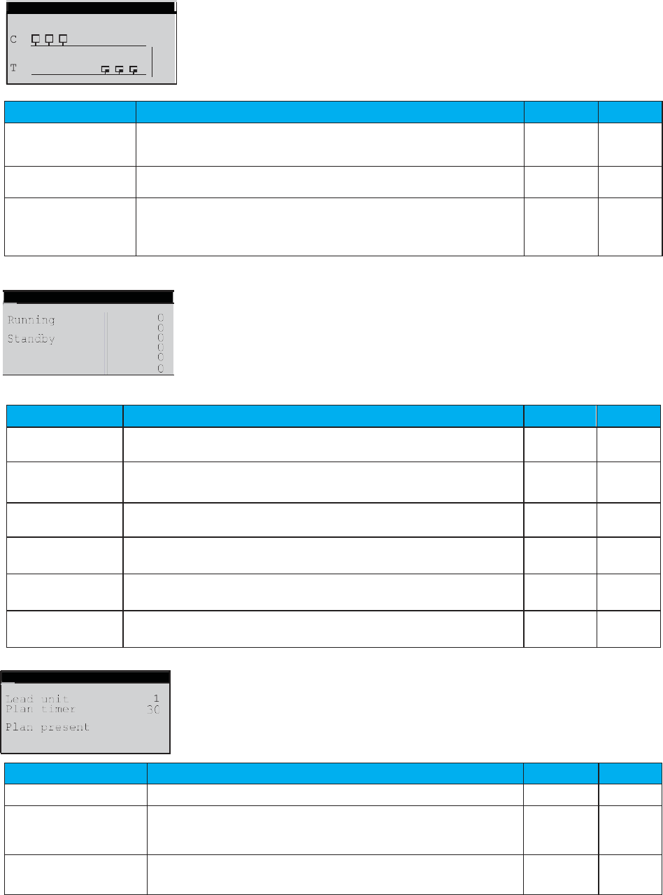
64
E2 Series Controller Operation Manual
Service>Group>Group Status (Screen 8)
This screen provides an overview of pLAN work group.
Display
Description
Variables
Default
Group Status Indicates if multiple A/C unit grouping is enabled.
On
Off
On
C 1 2 3 4 5 6 7 8
Indicates the address (1-8) of each controller in the pLAN.
1
T 5 6 7 8 9 0 1 2
Indicates the address (25-32) of the terminal for each controller in
the pLAN. The terminal address numbers range from 25 to 32 but
only the last digit appears in the screen.
32
Service>Group>Group Status (Screen 9)
This screen provides an overview of the current duty status for all the A/C
units combined in the group.
Display
Description
Variables
Default
Running
Display indicates how many units in the group are currently
operating
0 to 9
0
Active
Display indicates how many units in the group are currently
active
0 to 9
0
Standby
Display indicates how many units in the group are currently in
standby
0 to 9
0
Assist
Display indicates how many units in the group are currently
operating in the capacity assist mode
0 to 9
0
Online
Display indicates how many units in the group are currently
available to operate
0 to 9
0
Out of Service
Display indicates how many units in the group are not available to
operate
-
0
Service>Group>Plan timing (Screen 10)
The final step is to access the Service>Options>Group Setup screens
used to configure parameters that apply to how individual A/C units
interact in the work group.
Display
Description
Variables
Default
Lead unit
Display indicates which unit is currently the lead.
0 to 8
0
Plan timer
Display indicates the time delay (in seconds) between the
detection of a communication failure and the annunciation of a
Comm alarm.
0 to 60
30
Plan present Display indicates if a pLAN is detected by the controller.
No
Yes
No
Active
Assist
Online
Out of Service
Group Status
Yes
Plan timing
Group Status Off
1
2
3
4
5
6
7
8
5
6
7
8
9
0
1
2

65
E2
Series Controller Operation Manual
7.2.6.1
Group Sensor Values
This displays the current group temperature and humidity control values
transmitted from the Lead controller. The field below displays the selected
control T/H sensor arrangement (lead, avg, min, max, local) depending upon how
the group is set-up. See Service>Group screens, Section 7.2.6.
The last field shows the unit group address assigned to the controller within the
group and the address of the current lead controller.
7.2.6.2
Group Alarms
This screen only appears when the controller is wired with additional A/C unit
controllers. It displays bit mask values indicating the alarm conditions that will
initiate a group internal alarm causing the unit to switch over from “Active” to “Unit
Off”. See Service>Group (Alarms Set) earlier in Section 7.2.6.
7.2.6.3
Lead Controller Group Sensors
This screen appears only in the display of the controller that is designated as the
Lead in a multi-unit work group. The lead controller polls the Temperature and
Humidity sensors from all the A/C units in the work group and displays the
averaged values. It also displays the value of the minimum (lowest) temperature
sensor and the value of the minimum humidity sensor in the A/C group and
conversely, displays the value of the maximum (highest) temperature sensor and
maximum humidity sensor in the A/C group. The fields at the bottom are the
addresses of the controllers in the group that have the min. (lowest) and max.
(highest) temperature and humidity sensor readings.
7.2.6.4
Group Sensor Status
This screen appears only in the display of the controller that is designated as the
Lead in a multi-unit work group. It shows what sensors exist on each A/C unit for the
Lead controller to perform the group sensor averaging calculation. The numbers
are the sums of index values assigned to the sensors as shown in the following
key:
1 = Return Temperature Sensor
2 = Return Humidity Sensor
4 = Remote Temperature Sensor
8 = Remote Humidity Sensor
16 = Static Pressure Sensor
To determine which sensors are enabled and operable for each unit, determine which index numbers, derived from the key above,
will produce the number shown in the screen.
In the example shown, the number for the lead unit is 15. This results from adding 1 Return Temperature + 2 Return Humidity +
4. Remote Temperature + 8 Remote Humidity together, confirming those sensors are operable.
The number shown for unit number 2 is three, the result of adding 1 + 2. This confirms unit number 2's Return Temperature and
Return Humidity sensors are detected by the Lead controller. If a one appeared instead for unit number 2, it would indicate the
signal for the Return Humidity sensor is not present. That sensor is either not enabled or it has failed.
0
0
0
0
Unit5
Unit6
Unit7
Unit8
Lead Unit 1
15
0
3
0
0
Unit1
Unit1
Unit2
Unit3
Unit4
Group Sensor Status
Group T/H Sensors
Avg 000.0 °F 000.0 %
Min 000.0 °F 000.0 %
Max 000.0 °F 000.0 %
Min Temp 0 Min Hum 0
Max Temp 0 Max Hum 0
Group Alarm Setup
1-8: 000 9-16: 000
17-24: 000 25-32: 000
33-40: 000 41-48: 000
49-56: 000
See manual for details
Net T/H Sensors
00.0°F
00.0%rh
T/H Sensor Value
Local Unit 0 of 0
Lead: 1
66
E2 Series Controller Operation Manual
7.3 BMS Communication
When BMS communication is used, the controller must be
equipped with an optional expansion card designed for one
of a variety of serial communication protocols available. A
communication port on the expansion card (see Section 2.2.6)
allows the controller to be field connected to a central Building
Management System (BMS) for monitoring and control of data
points. An RS-485 serial port is for Modbus RTU or BACnet
MS/ TP protocols and a 10BaseT port is available for TCP/IP
based protocols such as BACnet over IP, BACnet over
Ethernet, SNMP or HTTP.
Supported Protocols Media Connections
BACnet IIP 10BaseT RJ45 direct
BACnet over Ethernet 10BaseT RJ45 direct
HTTP 10BaseT RJ45 direct
SNMP V1, V2c 10BaseT RJ45 direct
Modbus over IP 10BaseT RJ45 direct
SNMP V1, V2 10BaseT RJ45 direct
Modbus RTU twisted pair daisy chain
BACnet MS/TP twisted pair daisy chain
7.3.1 Direct BMS Control
The controller may be configured to accept proportional
analog signals that mimics a sensor. The controller will act on
that signal whether it comes from a real sensor or a BMS
analog output.
See the Addendum to the E2 Series Controller Manual For
CyberAiR (CFS) Systems, OCS0108 for the E² controller's
BMS parameters. Note that STULZ now publishes a point list
addendum whenever a new version of CyberAir E² software
is released, regardless of whether the points list has changed
since the previous software version.
7.3.2 BMS Communication
Direct
Connection
Daisy Chain
Connection
The Service>BMS Comm menu is used to set-up the
parameters to allow a BMS (BAS) interface for monitoring
controller operation for the serial-based networks such as
BACnet MS/TP. Units using the BACnet over IP, BACnet over
Ethernet, or HTTP protocols do not need to change anything
in this menu.
The BMS address and baud rate have meaning only on RS-
485 networks and with the serial protocols of Modem,
Modbus RTU, Commission, and Carel. The baud rate is fixed
for BACnet. Systems using a 10BaseT interface should use
the defaults of address 1, baud rate 19200, and protocol
lBACnet.
Certain Integer and Digital variables that start with BMS (see
Section 10.0) require that the BMS "keep alive" parameter
changes between 1 and 2 within a 10-minute span. The
general procedure is to set up variables like the BMS low fan
speed and then write a 1 to the BMS keep alive address.
BMS
Unit
Unit
Unit
BMS Communications
Address:
1
Baud Rate:
19200
Protocol:
BACnet
BMS keep alive:
1
BMS
Unit 1
Unit 2
Unit 3
Figure 13. BMS Connection Types
If multiple A/C units are grouped together, each controller
added to the group must be configured with a CPU address
for BMS communication. In the daisy chain configuration
an RS-485 twisted-pair connection is made from the BMS
to the first controller and an RS-485 connection from each
controller to the next; the connections form a common bus
and each E
2
controller listens on the bus and has a unique
address. The direct connection example is via TCP/IP over
Ethernet.
For complete details on using BMS control, contact
STULZ Product Support (see Section 9.0) and refer to
STULZ Controller Communications Manual, OCU0147.

67
E2
Series Controller Operation Manual
8.0 MAINTENANCE AND REPAIRS
8.1 General Maintenance
Because conditions vary greatly, individual maintenance
schedules must be determined for each location, based upon
periodic examination of the controller.
1. Check for corrosion on electrical connections.
2. Clean corrosion and apply anti-corrosion
grease.
3. Periodically, check and tighten all terminal connections.
A system should be established for trend analysis. Record all
problems, defects and deficiencies noted by operators and
discovered during maintenance inspections together with the
corrective actions taken. For maintenance assistance, contact
STULZ Product Support.
8.2 Troubleshooting
The STULZ E2 Series controller is designed for continuous
and dependable operation. In the event that a problem is
encountered with the A/C system, the system controller may
be used to diagnose the cause. The controller signals an alarm
condition when the red backlight LED is illuminated behind the
alarm function key.
An alarm indication is accompanied by a screen text message
with a brief description of the cause (See "5.3.4 Alarm Screen
Messages"). Often the remedy is simple to determine by
reading the alarm message Dirty Filter Alar (replace filter, for
example).
The following guidelines are included to assist in troubleshooting
the controller due to operational or performance problems. If
the problem can’t be resolved using the alarm screens and these
guidelines, contact STULZ Product Support for assistance
(See Section 9.0).
Problem: Control Is Erratic
1.
Wiring improperly connected or broken. Check wiring
against the schematic diagram included with the unit.
2.
Wires shorted. Check all wire connections to ensure they
are tight and that no shorts are present.
Problem: Alarm Lamp is ON
1.
Use the system controller to check the Alarm display
message(s).
2.
Identify and correct cause of alarm condition.
3.
Reset if necessary.
8.3 Repair Procedures
8.3.1 General
Under normal operating conditions and with the proper
preventive maintenance, the unit should provide excellent
service for many years. If necessary, the unit may be returned
to the manufacturer for major overhaul and refurbishment. All
work must be performed by qualified technicians.
8.3.2 Component Replacement
Replaceable components may be removed and replaced from
the controller using common hand tools. Ensure power is
disconnected from the controller before removing or replacing
components.
WARNING
Power may still be present inside the controller when the
On/Off switch on the A/C unit door is OFF.
WARNING
Turn off all power to the unit before conducting any
troubleshooting procedures, unless the procedure specifically
requires the system to operate. Keep hands, clothing and tools
clear of the electrical terminals.
68
E2 Series Controller Operation Manual
8.4 Control I/O Module Signal LED's
The GEN1 STULZ E2
controller includes 3 signal LED's (red, yellow and green) that provide information on the operation of the
control module and status of the connection to the pLAN. These signal LED's are positioned adjacent to the yellow, "Power On" LED
(see Figure 2). The signal LED's may be used for diagnostic purposes if a problem arises with the controller.
70
E2 Series Controller Operation Manual
9.0 PRODUCT SUPPORT
STULZ Product Support provides aftermarket technical and
field support, warranty authorization and part sales to
contractors and end users. Factory authorized services are
available by request and include:
Factory Authorized Start-up/Warranty
Inspection
Commissioning Assistance
Break/Fix Repair
Preventive Maintenance Contracts
Performance Evaluations
Technician and Owner Training
9.1 Factory Authorized
Start Up/ Warranty
Inspection
STULZ recommends purchasing Factory Authorized Start
Up/Warranty Inspection for all new STULZ precision cooling
equipment. Factory Authorized Start Up/Warranty
Inspection ensures that your equipment is installed and
operating per STULZ recommended guidelines. This
essential service guarantees that STULZ equipment has
the best warranty coverage available.
STULZ precision cooling equipment is covered by an industry
leading 24 Month Upgraded Parts Warranty and 90 Day
Labor Warranty once Factory Authorized Warranty
Inspection/Start- Up is performed and Start Up Checklists
are returned and validated by STULZ Product Support.
A Limited 12 Month Parts Only Warranty applies if Factory
Authorized Start Up/Warranty is not purchased and Start Up
Checklists are received from an unauthorized party and
validated by STULZ Product Support.
The STULZ Product Support coordinates all Factory
Authorized Services and ensures only STULZ certified
technicians are dispatched to perform your Factory
Authorized Start Up/Warranty Inspection.
Contact the STULZ Product Support with field service
requests at (888) 529- 1266 Monday through Friday from
8:00 a.m. to 5:00 p.m. EST.
9.2 Technical Support
The STULZ Technical Support Department is dedicated to
the prompt reply and resolution of issues experienced with
supplied equipment. Call (888) 529-1266 Monday through
Friday from 8:00 a.m. to 5:00 p.m. EST. After hours support
is also available. Provide your name and contact
information. A support technician will return your call.
When calling to obtain support, it is important to have the
following information readily available, (information is found
on the unit's nameplate):
Unit Model Number
STULZ Sales Order Number
STULZ Item Number
Unit Serial Number
Description of Problem
9.3 Obtaining Warranty Parts
All Warranty Parts Authorizations are validated and processed
through the Technical Support Department at (888) 529-
1266 Monday through Friday from 8:00 a.m. to 5:00 p.m. EST.
A support technician at STULZ will provide troubleshooting
assistance over the telephone. If it can be determined that
apart may be defective, a warranty authorization for a
replacement part will be processed by STULZ Technical
Support.
The replacement part will then be shipped via UPS ground. If
the customer requests that warranty part(s) be sent by any
other method than UPS ground, the customer is responsible
for the shipping charges. If you do not have established credit
with STULZ you must provide a freight carrier account number.
A written (or faxed) purchase order is required on warranty
parts and must be received prior to 12:00 p.m. for same day
shipment. The purchase order must contain the following
items:
Purchase Order Number
Date of Order
STULZ Stated Part Price
Customer Billing Address
Shipping Address
Customer's Telephone and Fax Numbers
Contact Name
Unit Model Number
Serial Number
STULZ Item Number
The customer is responsible for return shipping costs. Return
of defective part(s) must be within 30 days at which time an
evaluation of the part(s) is conducted and if the part is found to
have a manufacturing defect a credit will be issued.
When returning defective part(s), complete the Return Material
Authorization Tag and the address label provided with the
replacement part. For prompt processing, please affix the
RMA in a prominent place on the external packaging of the
returned part.
71
E2
Series Controller Operation Manual
9.4 Obtaining Spare Parts.
Spare and replacement parts requests are to be
made through Product Support by:
Fax: (301) 620-2606
Phone: (888) 529-1266
E-mail: (parts@stulz-ats.com)
Quotes are given for specified listed parts for a
particular unit.
STULZ accepts Visa and MasterCard. STULZ may extend credit
to its customers; a credit application must be pre- pared and
approved (this process could take up to one week).
A 25% minimum restocking charge will be applied on re- turned
stocked parts that were sold as spare/replacement parts. If the
returned part is not a stocked item, a 50% restocking charge may
be applied.
A Return Material Authorization Number (RMA) is required when
returning parts. To receive credit for returned repair or
replacement parts, the parts must be returned to STULZ within
30 days of the purchase date. Spare part sales over 30 days old
will be considered final and the parts will remain the sole property
of the ordering party.

72
E2 Series Controller Operation Manual
STULZ System Types
Term Definition
AHU Air Handling Unit
AHU AWS Air Handling Unit with Alternate Water Source option
AR Remote (split) Air cooled system
AR CH Remote (split) Air cooled Chiller
AR AWS Remote (split) Air cooled system with Alternate Water Source option
AS Self-contained air-cooled system
AWS Water Source option
CMU Coolant Modulating Unit
CW Chilled Water system
DAHU Dual Air Handling Unit
DAHU Dual Air Handling Unit with Alternate
DAR Dual Remote (split) Air cooled system
DAR AWS
Dual Remote (split) Air cooled system with Alternate Water Source
option
DAR OA Dual Remote (split) Air cooled system with Outside Air option
DCW Dual Chilled Water system
DW/DG Dual Water or Dual Glycol cooled system
DW/DG FC Dual Water or Dual Glycol cooled system with Free-cooling option
DW/DG OA Dual Water or Dual Glycol cooled system with Outside Air option
W/G Water or Glycol cooled system
W/G AWS Water or Glycol cooled system with Alternate Water Source option
W/G FC Water or Glycol cooled system with Free-cooling option

73
E2
Series Controller Operation Manual
Glossary
Term Definition Term Definition
ASHRAE
American Society of Heating,
Refrigerating, and Air-Conditioning
Engineers
IT Information Technology
BTUH/Hr
British Thermal Units Per Hour IOM Installation, Operation, and Maintenance Manual
CCD Compact-CWE Kw kilowatt
CFM Cubic Feet Per Minute kVA Kilo Volt Amps
CNDCT Conductor LWT Leaving Water Temperature
CRAC Computer Room Air Conditioner
MAX CKT
BKR
Maximum Circuit Breaker
CRAH Computer Room Air Handler
MAX
FUSE
Maximum Fuse
CW Chilled Water MCA Minimum Circuit Ampacity
DB Dry Bulb NEC National Electric Code
DF Downflow NFPA National Fire Protection Agency
EC Electronically Commutated PSI Phase
DP Dewpoint PSIG Pounds Per Square Inch
DX Direct Expansion Systems RLA Pounds Per Square Inch Gauge
ESD Electrostatic Discharge RMA Run Load Amps
EST Eastern Standard Time R-Value Return Material Authorization
ºF Degrees Fahrenheit SATS Thermal Resistance
FLA Full Load Amps SDS STULZ Air Technology Systems, Inc.
FOB Freight on Board SPDT Safety Data Sheet
HGBP Hot Gas Bypass UF Single Pole, Double Throw
HACR
Heating, Air Conditioning,
Refrigeration
UL Upflow
HP Horsepower UPS Underwriters Laboratories
HVAC
Heating, Ventilation and Air
Conditioning
V Uninterruptible Power Supply
HX Heat Exchanger VA Volt
Hz Hertz VAC Volt-Amperes
IAQ Indoor Air Quality VFD Volt, Alternating Current
in. w.g. Inches of Water Gauge W Variable Frequency Drive
EC Electronically Commutated PSI Watt(s)

North American Headquarters
STULZ Air Technology Systems, Inc.
1572 Tilco Drive | Frederick, MD 21704
301.620.2033 | Fax: 301.662.5487 | info@stulz-ats.com
Technical Support: 888.529.1266
www.stulz-usa.com
OZU0037M 2018 © STULZ Air Technology Systems, Inc. - Specifications subject to change without notice.
